 |
|
 |
Satish Lele leleequip@gmail.com |
- For Agitators / Mixers, factors to be considered for design are
Type of Agitation: Agitation can be Vigourous, Moderate or Mild. For Vigourous mixing, time required for total mixing can be few seconds. For Moderate mixing, time required for total mixing can be few minutes. For Mild mixing, time required for total mixing can be few hours. Degree of agitation increases with increase in number of revolutions of agitator and increase in impeller diameter.
Type of Agitator: Generally agitator is mounted vertically at the top of the tank. This is the normal practice for mounting an agitator in small and medium size tanks. Agitator can also mounted horizontally from side of a tank, called side entering agitator, for very large diameter storage tanks.
Pattern of Circulation: Axial or Radial. When a vessel is heated or cooled by coil or jacket, axial flow is prefered. When the contents are to be mixed, radial circulation is prefered. When both patterns of circulation are required, radual flow impeller is installed at the bottom of agitator shaft, while radial flow impeller is installed at the center of agitator shaft.
Location of agitator in the equipment: Generally agitator is centrally located for better flow pattern. Agitator is located off-center if some part of vessel is occupied by internal coil or some other internal.
Shape and size of tank: Vertical cylindrical vessel is the best type for installing an agitator. However, agitator is also installed in vertical rectangular tank, in water and waste water treatment tanks.
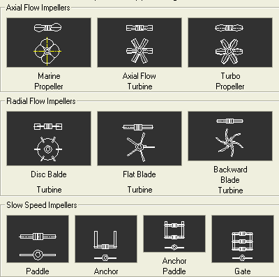
Impellers: There can be following simple Impellers. Marine Propeller, Axial Flow Turbine, Turbo Propeller, Disc Blade turbine, Flat Blade Turbine, Backward turned turbine, Paddle, Anchor, Anchor/Paddle or Gate. Main parts of impeller are hub and blades. Hub is installed on the shaft by shaft key and grub screw. Impellers may be one piece or split into two or many pieces, bolted together. Marine Propeller is generally a casting. All other impellers are of fabricated construction and can be either Bolted or Welded type.
Diameter of Impeller: Diameter of impeller depends on diameter of tank. Diameter of impeller is generally 1/3rd the diameter of the tank for
- Marine Propeller
- Axial flow turbine
- Turbo Propeller
- Disc Blade turbine
- Flat Blade turbine
- Backward Blade turbine
- Paddle
- Anchor
- Anchor/Paddle
- Gate
Baffles / Coils: Generally 4 baffles are provided in a vertical cylindical vessel for good mixing in case of first 6 (axial flow) impellers. For last 4 (radial flow), no baffles are provided. Coils are provided in some vessels, for heating or cooling. Baffles and coil reduce effective diameter of the vessel.
Power required for agitation: Power depends on diameter of impeller, revolutions of agitator shaft, power number of impeller, number of impellers, density, content of solids and viscocity of liquid.
Overhang of shaft and lower fixed bearing: The shaft is supported at the top end by bearing housing assembly. The lateral movement of impeller at the bottom of the shaft, tries to bend the shaft, if shaft is long (more than 3 meters). To avoid this a bottom bearing is provided. Lower fixed bearing is a non rotating bearing, made of a sleeve of softer metal or plastic material.
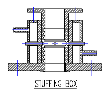
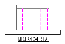
Type of Seal: Stuffing Box or Mechanical Seal: A seaing arrangement is provided in a closed vessel, along agitator shaft at the top. Seaing arrangement does not allow vapours to leak out of vessel, along the rotating shaft. Seaing arrangement can be of two types.
Stuffing Box: Stuffing Box has two shells. The diameter of inner shell is larger than diameter of shaft. 3 or 4 packing rings are installed in this gap at bottom, followed by latern ring on top and 3 or 4 packing rings on top. Packing rings act as sealant while latern ring can provide lubrication to shaft. The top rings are pressed from top by a ring. Cooling water flows in outer shell, which keeps the packing rings and lantern ring cool. Stuffing Box fits diectly on top of closed vessel inside the stool on base plate.
Mechanical Seal: Mechanical Seal is similar to stuffing box, but in this mechanical seals are provided in place of packing rings. Mechanical seal assembly is readily avaible as one unit. Mechanical Seal can have one mechanical seal (Single mechanical seal unit) or two mechanical seals (Double mechanical seal unit). In Double mechanical seal unit, one mechanical seal is at top and one mechanical seal at bottom. Double mechanical seal provides better sealing along the agitator shaft. Double mechanical seal is used in case of vessels having high vacuum inside or if vapours are corrosive. Double mechanical seal is expensive and difficult to mentain.
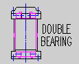
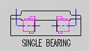
Number of Bearings on Shaft: There can be bearing housings with 2 or 1 bearings. For agitators having short length, there can be no bearing housing.
Double Bearing Housing: A bearing housing in which 2 ball bearings are installed, called double bearing housing. Double Bearing Housing is prefered as double bearing housing reduces deflection of shaft. Double Bearing Housing is normally used for shafts rotating at higher speeds, with Marine Propeller, Axial flow turbine, Turbo Propeller, Disc Blade turbine, Flat Blade turbine, Backward Blade turbine Impellers. One bearing is installed at the top and one bearing at bottom. Arrangement for greasing the bearings is provided for both bearings.
Single Bearing Housing: A housing in which only one ball bearings are installed, is called single bearing housing. Single bearing housing is prefered as single bearing housing reduces deflection of shaft. Single bearing housing is normally used for shafts rotating at slow speeds, with Paddle, Anchor, Anchor/Paddle, Gate impellers.
Drive Assembly:
A number of combinations are possible, based on speed of drive motor and rotational speed of shaft of agitator.
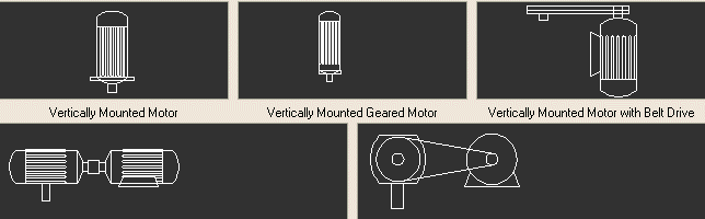
Vertically mounted motor: Vertically mounted motor is mounted on top of stool. Vertically mounted motor is used when rotational speed of shaft of agitator is same as that of motor.
Vertically mounted geared motor: Vertically mounted geared motor is mounted on top of stool. Vertically mounted geared motor is used when rotational speed of shaft of agitator is same as that of reducing gear integral with motor.
Horizontally mounted motor with pulleys and V belts: Horizontally mounted motor with pulleys and V belts is mounted on the side of stool. Horizontally mounted motor with pulleys and V belts is used when rotational speed of shaft of agitator is not the same as that of motor. A combination of pulleys of different diameters, with V belts, reduces the rotational speed of shaft of agitator to required speed.
Directly coupled horizontal gearbox and motor: Directly coupled horizontal gearbox and motor is mounted on the top of stool. Gearbox is mounted directly on top of stool and motor is placed on side platform. Directly coupled horizontal gearbox and motor is used when rotational speed of shaft of agitator is same as output speed of gearbox.
Horizontal gearbox and motor coupled by pulleys and V belts: Horizontal gearbox and motor coupled by pulleys and V belts is mounted on the top of stool. Gearbox is mounted directly on top of stool and motor is placed on side platform. Pulleys and V belts are used to get exact input speed of gearbox. Horizontal gearbox and motor coupled by pulleys and V belts then matches rotational speed of shaft of agitator with the output speed of gearbox.
Mixing by agitators: Mixing by agitators takes place by momentum transfer. Marine Propeller, Axial Flow Turbine, Turbo Propeller, Flat Blade Turbines, have smaller blade area and these rotate at relatively high speeds (100 to 400 RPM). These are used to mix liquids with low viscosity. Agitators having large blade area like Paddle, Anchor, Anchor/Paddle or Gate rotate at lower speeds (40 to 50 RPM). These are used to mix liquids with high viscosity. Top entering agitators are used for smaller size vessels (1,000 to 10,000 liters) and for applications involving higher power requirements per unit volume. Side entering are installed in storage tanks having large diameters (more than 10 meters), with non-corrosive liquids, especially in tanks which store Crude Petroleum.
Type of Agitators and their functionsMarine Propeller is generally an item produced by casting process in a foundry. Marine Propeller has 3 or 4 blades. Cast agitators have two basic advantages, uniformity of material and hard surface. Marine Propellers have tapering blades, and angle of blade varies from root to tip. Tapering blades produce maximum axial flow. The diameter of Marine Propeller impeller is 15% to 30% of diameter of tank. These have tip speeds between 300 to 500 meters per minute.
Axial Flow Turbine, Turbo Propeller and Flat Blade Turbine have blades ranging from 3 to 6. Propeller and Flat Blade Turbine have tip speeds between 200 to 300 meters per minute. The diameter of impeller is 25% to 60% of tank diameter. For Axial Flow Turbine and Turbo Propeller, the angle of blade varies from 30 degrees (for less viscous liquids) to 60 degrees (for more viscous liquids). Standard angle is 45 degrees. Power requirement increases with higher pitch angle. For Flat Blade Turbine, the length of blade is 25% of diameter, and disk diameter is 60% to 70% of the diameter of impeller.
Paddle, Anchor, Anchor/Paddle or Gate have only 2 blades. Blades extend close to the tank wall and have tip speeds between 80 to 150 meters per minute. Blades push and rotate the liquid in a laminar flow. There is no axial or radial mixing. The width of blade is 1/8th or 1/10th of the agitator diameter.
There are more complex impellers like helical screws, cones and high speed discs.
There can be one or more impellers on shaft. Number of impellers = (Maximum liquid height x average specific gravity) / Diameter of tank. The gap between two impellers = Liquid height / (Number of impellers - 0.5).
Most important parameters are diameter and length of agitator shaft and impeller diameter. These are decided by process design calculations.
Couplings used for connecting agitator shaft to drive shaft is rigid coupling.
Material of construction for wetted parts can be Stainless Steel, Carbon Steel or other metals and alloys. SS liner is provided on CS base plate if wetted parts are SS.
Top and bottom stool is provided for housing stuffing box or mechanical seal and Bearing Housing. Base Plate is provided to install assembly on it.
For Vertical Cylindrical Vessels
Vessel Volume = (pi * vessel dia * vessel dia * vessel len) / 4.0
Agitator Shaft length = vessel length + (vessel dia * 0.25)
For Rectangular Tanks
Tank Volume = Vessel Length * Vessel Breadth * Vessel Height
Agitator Shaft length = Vessel Height
You have to then find out Viscocity and Specific Gravity of Liquid that will be in the vessel
Based on Viscocity and Specific Gravity of Liquid, design will depend on Reynold's Number.
If the liquid is very viscous (viscocity = 500 to 1000 cp) the Reynold's Number can be in laminar zone. For this range, Reynold's Number is less than 2000.
If the liquid is less viscous (viscocity = 100 to 500 cp) the Reynold's Number can be in laminar zone. For this range, Reynold's Number is 2000 to 10,000.
If the liquid is not viscous (viscocity = 1 to 100 cp) the Reynold's Number can be in turbulent zone. For this range, Reynold's Number is greater than 10,000.
Based on geometry of vessel, many factors for impeller can be decided.
- Marine Propeller:
Agitator speed or RPM of shaft is prefered as 100 or 200 or 300. This speed is easier to achieve with motor/gearbox combination.
Power number, which decides power required for mixing, is 0.3 for 3 bladed and 0.33 for 4 bladed impeller.
Pumping factor, which decides flow rate of mixing, is 0.33 for 3 bladed and 0.34 for 4 bladed impeller.
Diameter of impeller is generally 1/3rd the diameter of the tank
- Axial flow turbine:
Agitator speed or RPM of shaft is prefered as 100 or 200 or 300. This speed is easier to achieve with motor/gearbox combination.
Power number, which decides power required for mixing, is 1.35 for 3 bladed, 1.4 for 4 bladed, 1.45 for 5 bladed, 1.5 for 6 bladed impeller.
Pumping factor, which decides flow rate of mixing, is 0.6 for 3 bladed 0.69 for 4 bladed, 0.78 for 5 bladed, 0.87 for 6 bladed impeller.
Diameter of impeller is generally 1/3rd the diameter of the tank
- Turbo Propeller:
Agitator speed or RPM of shaft is prefered as 100 or 200 or 300. This speed is easier to achieve with motor/gearbox combination.
Power number, which decides power required for mixing, is 1.35 for 3 bladed, 1.4 for 4 bladed, 1.45 for 5 bladed, 1.5 for 6 bladed impeller.
Pumping factor, which decides flow rate of mixing, is 0.6 for 3 bladed 0.69 for 4 bladed, 0.78 for 5 bladed, 0.87 for 6 bladed impeller.
Diameter of impeller is generally 1/3rd the diameter of the tank
- Disc Blade turbine:
Agitator speed or RPM of shaft is prefered as 100 or 200 or 300. This speed is easier to achieve with motor/gearbox combination.
Power number, which decides power required for mixing, is 5.0.
Pumping factor, which decides flow rate of mixing, is 0.7 to 0.8.
Diameter of impeller is generally 1/3rd the diameter of the tank
- Flat Blade turbine:
Agitator speed or RPM of shaft is prefered as 100 or 200 or 300. This speed is easier to achieve with motor/gearbox combination.
Power number, which decides power required for mixing, is 5.0.
Pumping factor, which decides flow rate of mixing, is 0.7 to 0.85.
Diameter of impeller is generally 1/3rd the diameter of the tank
- Backward Blade turbine:
Agitator speed or RPM of shaft is prefered as 100 or 200 or 300. This speed is easier to achieve with motor/gearbox combination.
Power number, which decides power required for mixing, is 5.0.
Pumping factor, which decides flow rate of mixing, is 0.65 to 0.85.
Diameter of impeller is generally 1/3rd the diameter of the tank
- Paddle:
Agitator speed or RPM of shaft is prefered as 50. This speed is easier to achieve with motor/gearbox combination.
Power number, which decides power required for mixing, is 5.0.
Pumping factor, which decides flow rate of mixing, is 0.03.
Diameter of impeller is generally 80% the diameter of the tank
- Anchor:
Agitator speed or RPM of shaft is prefered as 50. This speed is easier to achieve with motor/gearbox combination.
Power number, which decides power required for mixing, is 5.0.
Pumping factor, which decides flow rate of mixing, is 0.05.
Diameter of impeller is generally 80% the diameter of the tank
- Anchor/Paddle:
Agitator speed or RPM of shaft is prefered as 50. This speed is easier to achieve with motor/gearbox combination.
Power number, which decides power required for mixing, is 5.0.
Pumping factor, which decides flow rate of mixing, is 0.07.
Diameter of impeller is generally 80% the diameter of the tank
- Gate:
Agitator speed or RPM of shaft is prefered as 50. This speed is easier to achieve with motor/gearbox combination.
Power number, which decides power required for mixing, is 5.0.
Pumping factor, which decides flow rate of mixing, is 1.0.
Diameter of impeller is generally 80% the diameter of the tank
For Marine Propeller, Axial flow turbine, and Turbo Propeller, based on the Type of Impeller, Agitator speed and Reynold's number selected, my program will calculate the diameter of the impeller. My program reitirates till the width factor of impeller diameter to vessel diameter, is achieved by increasing or decreasing the agitator speed. My program will indicate the calculated agitator speed and diameter of impeller. You can round up agitator speed and diameter up to nearest value.
Output Speeds of 1500 rpm Motor with Gearbox are : 300, 200, 150, 120, 100, 75, 60, 50, 43, 37 30, 25, 22.
Output Speeds of 1000 rpm Motor with Gearbox are : 200, 133, 100, 80, 67, 50, 40, 33, 29, 25, 20, 17, 14.
Output Speeds of 750 rpm Motor with Gearbox are : 150, 100, 75, 60, 50, 38, 30, 25, 21, 19, 15, 13, 11.
Output Speeds of Direct coupled Motor are : 1500, 1000, 750.
For any other speeds use, Motor + V Belt Drive.
My program then calculates pumping rate. Pumping rate = (pumpfac * (shaft rpm / 60.0) * impeller od3) in cu mm / sec. My program then calculates Mixing time = Vessel Volume / Pumping Rate. My program indicates the value of mixing time. You can choose mixing time as per your requirements.
My program will recalculate the diameter of the impeller and shaft rpm. You can choose these per your requirements.
My program asks for number of impellers on shaft. If these are more than one, program will recalculate the diameter of the impeller. You can round up diameter of the impeller as per your requirements.For Disc Blade turbine, Flat Blade turbine and Backward Blade turbine, diameter of impeller depends on Width factor to Vessel Diameter. My program calculates Impeller OD and indictes it.
Tip speed of impeller = 175 meters per minute, or 500 feet per minute. Agitator Speed depends on tip speed of impeller. My program calculates RPM of agitator.For Paddle, Anchor, Anchor/Paddle and Gate: Diameter of impeller depends on Width factor to Vessel Diameter. My program calculates Impeller OD. Tip speed of impeller = 82.5 meters per minute or 250 feet per minute. Agitator Speed depends on tip speed of impeller. Program calculates RPM of agitator.
My program then calculates the power absorbed for mixing. If the shaft RPM is less than 300, based on the absorbed power (output power of gearbox) and output RPM of gearbox, My program selects gearbox. My program indicates selected size of gearbox, which can be changed to next higher or lower value. My program then calculates diameter of shaft. You can select 4 types of materials for shaft. Indicated values of Yield Stress and Elastic Limit, in Kgs/ mm2 are as follows. My program then calculates maximum Bending Moment is at the end of shaft, Average Bending Moment at the end of shaft and Polar modulus of the shaft in cubic mm. My program then recalcuates Diameter of Impeller based on Critical Speed, and indicates recommended Impeller OD for Critical Speed. My program then reiterates till elastic limits is less than permisiible value by increasing shaft diameter. My program then calculates Critical Speed of Impeller. My program then reiterates till critical speed is more or less than 20% of agitator speed by increasing shaft diameter.
Absorbed Power in HP = (specific gravity * 1000 * number of impellers * power number * (shaft rpm / 60.0)3 (impod / 1000.0)5 * 1.1 * 1.2) / (9.81 * 75.0)
Carbon Steel: Shear Stress 30.0, Elastic Limit 170.0.
EN8: Shear Stress 55.0 Elastic Limit 246.0
EN24: Shear Stress 80.0 Elastic Limit 320.0
Stainless Steel: Shear Stress 50.0 Elastic Limit 230.0
You can select Safety Factor for calculation of shaft diameter.
Torque at end of shaft = (746 * motor hp) / (2 * pi * (rpm / 60)) [in N-mt]
Bending Moment = Torque * Safety Factor [in N-mm]
Force at the end of impeller blade, Fm = Bending Moment / (0.75 * 0.5 * Impeller Dia)
My program then indicates Final values after calculation of Critical Speed, Shaft RPM, Impeller Diameter and Shaft Diameter.
My programs run well in in these inexpensive CAD Programs. Download Trial Programs of either BricksCAD Lite or ProgeCAD or IntelliCAD or Draftsight or CADLogic or ZWCAD or FreeCAD, to check sefulness of my packages.  to Download Trial Agitator Package. Package can also run well in AutoCAD, upto AutoCAD 2010 but can not run on AutoCAD LT. to Download Loading Instructions for Agitator Package.
to Download Catalog for Agitator for metric.
to Download Catalog for Agitator for Foot-inch.
to Download Information about Agitator.
 Heat Exchanger Manual
