How to access Lisp Editor?: It can be accessed through Tools of AutoCAD window. Click on tools. click on autolisp editor and then on visual lisp editor. Or at command prompt type vlisp and press enter. Open a new file and save with some name. You enter your code in this page.
Lisp means List Processing. A list is some entities enclosed by starting and ending parenthesis ( ). First element is a sub routine in most of the cases. A simple but very useful program can be written using few built in functions or sub routines.
First one is
Defun or define a function. It clubs together a bunch of orders into one unit which can be accessed by function name. It starts with opening parenthesis followed by defun, followed by program name and then followed by two empty parenthesis. (defun prog_name ()
There can be some entities in empty parenthesis, which we will learn later. there can be some program code and at the end it has closing parenthesis of defun.
You can quickly check closing parenthesis. While the pointer is located at opening parenthesis, you can go to matching parenthesis, by clicking } while pressing control button. It shows matching parenthesis.
Semicolon can be used to write a comment. Everything written after Semicolon is ignored by AutoCAD. Please note that Lisp routines appear in BLUE colour.
First program can be a simple program of drawing a box, which is a rectangle having length of 6 units and height of 4 units. It is drawn by 4 points. p0. p1. p2 and p3.
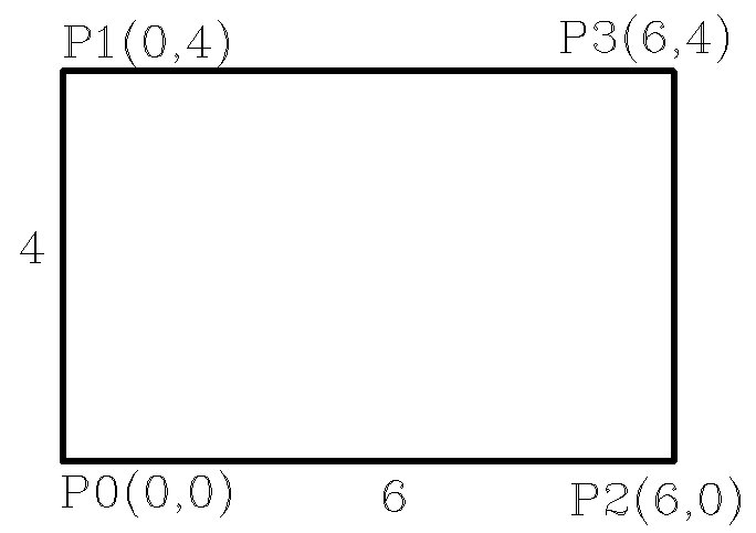
To start with let us start with coordinates of p0 as (0,0). Hence coordinates of p1 are (0,4). coordinates of p2 are (6,0). and coordinates of p3 are (6,4). For 2 dimensional drawing you need not define z coordinate.
The program starts with defun mybox. Now you can assign values for variables of 4 points. A value is assigned to a variable by setq. Setq needs a pair of entities. variable name and value to be assigned to it.
Notice colour of setq. It is written as list, which has starting and ending parenthesis and first element of list is a sub routine setq. p0, p1, p2 and p3 are variables to which value will be assigned. Values of all points are point list. A list sub routine creates a list. its syntax is (list entity1 entity2 . . .).
Here a point list is created with two entities. x coordinate and y coordinate. hence point list can be created by (list 0 0). (list 0 4). (list 6 0). and (list 6 4). Note that there should no comma separating two entities.
setq can be clubbed together using pairs of variables and values. Note the starting and ending parenthesis of setq.
Now we can draw a box using AutoCAD's line command. (command "_line" p0 p1 p3 p2 p0 ""). Note that commands is in quote marks. It follows with underscore. Due to this, AutoCAD programs written for other languages like German, French etc. can understand it as line command.
Note that variables are not in quote marks and not separated by comma. Last empty double quote acts as enter to finish line command. it can also be written as (command "_line" p0 p1 p3 p2 "c"). Indenting is done by tab for clarity.
Now in this program, variables p0 p1 p2 and p3 should loose their values when program ends. Otherwise these can remain in memory and interfere in other programs. These can be made to loose their value by making them local variables. It is done by adding them after a slash in empty parentheses after function name.
System variable cmdecho. If this set to 0, then all the actions at command line are not shown. It can be set by setvar or set vaiable. Its syntax is (setvar �cmdecho� 0). It suppresses all these messages.
princ subroutine shows a string on command line. (princ �string�). However (princ) does not show anything on screen. It should be added as last line in function to suppress return value of function which is generally �nil�.
Now let us modify this program by getting some values and manipulating point lists. You can manipulate point list using car and cadr. sub routine car returns first element of a list which is x co-ordinate and cadr returns second element of a list which is y co-ordinate.
x co-ordinate of p1 is same as x co-ordinate of p0 and y co-ordinate of p1 is y co-ordinate of p0 plus 4. hence p1 list can be created as (list (car p0) (+ (cadr p0) 4.0)). Similarly p2 list can be created as (list (+ (car p0) 6.0) (cadr p0)). p3 list can be created as (list (+ (car p0) 6.0) (+ (cadr p0) 4)). or (list (car p2) (cadr p3))
Now let us see some "get" subroutines, used for this program. getpoint asks to select a point on screen or you can input coordinates at command prompt like 3.5,5.0. Its syntax is (getpoint "string"). String appears at command prompt and program pauses for user entry of point. It returns a point list of selected point.
It is saved as one variable. In this case it is point p0. (setq p0 (getpoint "\nSelect lower left point of box")). \n writes the string on next line. There are two more "get" sub routines, used for this program. (getint "string") and (getreal "string"). getint returns the value of number entered as integer.
If you enter a real number, only integer part is returned. getreal returns the value of number entered as real number. if you enter a integer, it is returned as real number. Hence you should always use getreal rather than getint. (getreal "\nEnter length of the box: ") and store it as distx1.
Similarly, (getreal "\nEnter height of the box: ") and store it as disty1. Now you can use these values to manipulate points p1, p2 and p3. add these to list of local variables.
You can have variation of this program. You can defun function as C:box. If you define it this way it can act like an AutoCAD command.
How to load the program?. I have saved the program file as al01.lsp. lsp extension is automatically added. To load the lisp file at command prompt type (load "al01.lsp") and press enter. If the file is in same folder as drawing, it automatically gets path, or else you have to give full path or add that folder by Support file search path throgh tools in AutoCAD.
You can add that folder by Support file search path through tools in AutoCAD.
There is option to load it through Lisp editor while writing the program. Click on file down arrow. The file will be loaded to current drawing.
Now to run the program type (box) and press enter if you have named it as box. or type box and press enter, if you have named it c:box. You will get these messages at command prompt, if cmdecho is not set to 0. A box will be drawn in drawing.
Now let us modify the mybox program with input arguments. These are fed to program, while calling the program. These are written in first list before slash. These are passed on to same variables used in program. These are considered as local variables for that program.
Now the program can be run as (box distx1 disty1) and you can run the program by (mybox 6.0 4.0) and press enter. you can even input a point list as argument for p0. However, you can not define the function as C: mybox.
There are 4 important Mathematical Operators. These are first in a list.Plus. Minus. Multipy and devide.
Plus and Minus opertaor. In case of plus operator, (+ number1 number2 number3 �..) each number after first is added to number1. In case of minus operator, (- number1 number2 number3 �..),
each number after first is subtracted to number1. Hence in effect all numbers after first are added and then subtracted from first number.
multiply and divide opertaor. In case of multiply operator, (* number1 number2 number3 �..), each number after number1 is multiplied to number1. In case of divide operator, (/ number1 number2 number3 �..), each number after number1 divides number1. Hence in effect all numbers after number1 are multiplied and then this number divides number1.
Now let us see two important programs based on arguments. In Autolisp, all angles are input in Radians and not Degrees. Hence function dtr, degrees to radians, is very useful. Here argument a is angle value in degrees. (defun dtr ( a ) (* pi (/ a 180.0))). Its reverse is rtd, radians to degrees. (defun rtd ( a ) (* (/ a pi) 180.0))
You can write all functions in one lsp file.
Program for baseplate.
Dimension location points.
 Now we will see the programs line by line.
(defun mybox ( / p0 p1 p2 p3 distx1 disty1)
(setvar "cmdecho" 0)
(setq p0 (getpoint "\nSelect lower left point of box: ")
distx1 (getreal "\nLength of baseplate: ")
disty1 (getreal "\nThickness of baseplate: ")
p1 (list (car p0) (+ (cadr p0) disty1))
p2 (list (+ (car p0) distx1) (cadr p0))
p3 (list (+ (car p0) distx1) (+ (cadr p0) disty1))
)
(command "_line" p0 p1 p3 p2 p0 "")
(princ)
)
|
(defun dtr ( a ) (* pi (/ a 180.0)))
(defun rtd ( a ) (* (/ a pi) 180.0))
|
(defun baseplate ( / p1 p2 p3 p4 p5 p6 p7 p8 p9 p10
p11 p12 p13 p14 p15 p16 p17 p18 p19 p20
p21 p22 p23 p24 p25 p26 p27 p28 p29 p30
p31 p32 pd1 pd2 pd3 pd4 pd5 pd6 pd7
distx1 distx2 distx3 disty1 disty2 dia1 dia2
)
(setq p0 (getpoint "\nSelect lower center point of baseplate: ")
distx1 (getreal "\nLength of baseplate: ")
disty1 (getreal "\nThickness of baseplate: ")
p1 (list (- (car p0) (/ distx1 2.0)) (cadr p0))
p2 (list (+ (car p0) (/ distx1 2.0)) (cadr p0))
p3 (list (- (car p0) (/ distx1 2.0)) (+ (cadr p1) disty1))
p4 (list (+ (car p0) (/ distx1 2.0)) (+ (cadr p1) disty1))
distx2 (getreal "\nDistance between Baseplate Holes: ")
p5 (list (- (car p0) (/ distx2 2.0)) (cadr p1))
p6 (list (+ (car p0) (/ distx2 2.0)) (cadr p2))
p7 (list (- (car p0) (/ distx2 2.0)) (cadr p3))
p8 (list (+ (car p0) (/ distx2 2.0)) (cadr p4))
dia1 (getreal "\nDiameter of Hole in base: ")
p9 (list (car p5) (- (cadr p5) (/ dia1 2.0)))
p10 (list (car p6) (- (cadr p6) (/ dia1 2.0)))
p11 (list (car p7) (+ (cadr p7) (/ dia1 2.0)))
p12 (list (car p8) (+ (cadr p8) (/ dia1 2.0)))
p13 (list (- (car p5) (/ dia1 2.0)) (cadr p5))
p14 (list (+ (car p5) (/ dia1 2.0)) (cadr p5))
p15 (list (- (car p6) (/ dia1 2.0)) (cadr p6))
p16 (list (+ (car p6) (/ dia1 2.0)) (cadr p6))
p17 (list (- (car p7) (/ dia1 2.0)) (cadr p7))
p18 (list (+ (car p7) (/ dia1 2.0)) (cadr p7))
p19 (list (- (car p8) (/ dia1 2.0)) (cadr p8))
p20 (list (+ (car p8) (/ dia1 2.0)) (cadr p8))
distx3 (getreal "\nWidth of top part: ")
p21 (list (- (car p0) (/ distx3 2.0)) (cadr p7))
p22 (list (+ (car p0) (/ distx3 2.0)) (cadr p8))
disty2 (getreal "\nHeight of Center of Hole: ")
p23 (list (car p21) (+ (cadr p21) disty2))
p24 (list (car p22) (+ (cadr p22) disty2))
p25 (list (car p0) (+ (cadr p0) (+ disty1 disty2)))
p26 (list (car p0) (+ (cadr p0) (+ disty1 disty2 (/ distx3 2.0))))
dia2 (getreal "\nDiameter of main Hole: ")
p27 (list (- (car p25) dia2) (cadr p25))
p28 (list (+ (car p25) dia2) (cadr p25))
p29 (list (car p25) (+ (cadr p25) dia2))
p30 (list (car p25) (- (cadr p25) dia2))
p31 (list (- (car p25) (/ dia2 2.0)) (cadr p25))
p32 (list (+ (car p25) (/ dia2 2.0)) (cadr p25))
pd1 (list (car p0) (- (cadr p0) disty1))
pd2 (list (car p0) (- (cadr p0) (/ disty1 2.0)))
pd3 (list (car p0) (+ (cadr p0) (/ disty1 2.0)))
pd4 (list (- (car p1) disty1) (cadr p1))
pd5 (list (+ (car p22) dia2) (cadr p22))
pd6 (list (car p11) (+ (cadr p7) disty1))
pd7 (list (car p30) (+ (cadr p30) dia1))
)
(command "_linetype" "set" "continuous" ""
"_line" p1 p2 p4 p3 p1 ""
"_line" p21 p23 ""
"_line" p22 p24 ""
"_arc" p24 p26 p23
"_circle" p25 (/ dia2 2.0)
"-linetype" "set" "hidden" ""
"_line" p13 p17 ""
"_line" p14 p18 ""
"_line" p15 p19 ""
"_line" p16 p20 ""
"-linetype" "set" "center" ""
"_line" p9 p11 ""
"_line" p10 p12 ""
"_line" p27 p28 ""
"_line" p29 p30 ""
"_linetype" "set" "continuous" ""
"_dim1" "hor" p1 p2 pd1 ""
"_dim1" "hor" p9 p10 pd2 ""
"_dim1" "hor" p21 p22 pd3 ""
"_dim1" "ver" p1 p3 pd4 ""
"_dim1" "ver" p22 p24 pd5 ""
"_dim1" "hor" p17 p18 pd6 ""
"_dim1" "hor" p31 p32 pd7 ""
)
)
|

 Back
Back