Body: The selection of material to fabricate the interior of the valve body is important. It depends on process chemicals flowing through the valve. There is often a choice with regard to the body and trim (moving parts like stem, seat and plug), and some valves may be obtained with the entire interior of the body lined with corrosion-resistant material. Valves are connected to pipe, fittings or vessels by their body ends, which may be flanged, screwed, butt or socket weld type, or finished for hose or sleeve coupling. Jacketed valves are also available.
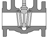 Disc, Seat and Port: These components are used directly for stopping and regulating the flow. The moving part directly affecting the flow is termed as disc, regardless of its shape. The non-moving part it bears on, is termed as the seat. The port is the maximum internal opening for flow (that is, when the valve is fully open). Discs may be actuated by conveyed fluid or moved by stem having a linear, rotary or helical movement. The stem can be moved manually or driven hydraulically, pneumatically or electrically, under remote or automatic control, or mechanically by weighted lever, springs etc.
Stem: There are two types of screwed stems, the rising stem and non-rising stem. These are moved by hand-wheel. Rising Stem generally for gate and globe valves) are made either with inside screw (IS) or outside screw (OS). The OS type has a yoke on the bonnet and the assembly is referred to as outside screw and yoke (OS and Y). The hand-wheel can either rise with the stem, or the stem can rise through the hand wheel. Non-rising stem valves are of Gate type. The hand wheel and the stem are in the same position whether the valve is open or closed. The screw is inside the bonnet and in contact with conveyed fluid. A Floor Stand is a stem extension for use with both types of stem, where it is necessary to operate a valve through a floor or platform. Alternately, rods fitted with universal joints may be used to bring a valve hand wheel within an operator's reach. Depending on the size of the required valve and availability, selection of stem type can be based on:
Whether it is undesirable for the conveyed fluid to be in contact with the threatened bearing surfaces.
- Whether an exposed screw is liable to be damaged by abrasive atmospheric dust.
- Whether it is necessary to use if the valve is open or closed.
In addition to the preceding types of stem used with gate and globe valves, most other valves have a simple rotary stem. Ball, plug and butterfly valves have a rotary stem which is moved by a permanent lever, or tool applied to a square boss at the end of the stem.
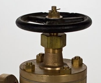
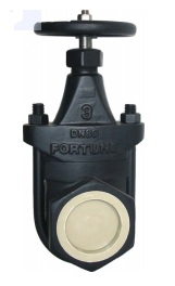
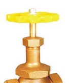
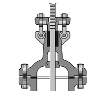 Bonnet: There are three basic types of attachments for valve bonnets: screwed (including union), bolted and breech lock. A screwed bonnet may occasionally stick and turn when a valve is opened. Although sticking is less of a problem with the union type bonnet, valves with screwed bonnets are best reserved for services presenting no hazard to personnel. Union bonnets are more suitable for small valves requiring frequent dismantling than the simple screwed type. The bolted bonnet has largely displaced screwed and union bonnet valves in hydrocarbon applications. A U-bolt or clamp type bonnet is offered on some small gate valves for moderate pressures, to facilitate frequent cleaning and inspection. The pressure seal is a variation of bolted bonnet used for high pressure valves, usually combined with OS and Y construction. It makes use of line pressure to tighten and seal an internal metal ring or gasket against the body. A critical factor for valves used for process chemicals is the lubrication of the stem. Care needs to be taken for selection of packing, gland design and choice of lubricant. As an option the bonnet may include a Lantern Ring which serves two purposes, either to act as a collection point to drain off any hazardous seepages, or as a point where lubricant can be injected. The breech lock is a heavier infrequently used and more expensive construction, also for high pressure use, and involves seal welding of the bonnet with the body.
Seal: In most stem operated valves, whether the stem has rotary or linear movement, packing or seals are used between stem and bonnet (or body). If high vacuum or corrosive, flammable or toxic fluid is to be handled, the disc or stem may be sealed by metal bellows, or by a flexible diaphragm (the later is termed pack-less construction).A gasket is used as seal between a bolted bonnet and valve body. Flanged valves use gaskets to seal against the line flanges. Butterfly valves may extend the resilient seat to also serve as line gaskets. The pressure-seal bonnet joint utilizes the pressure of conveyed fluids to tighten the seal.
Operator: This is a device which opens or closes a valve. Different devices are available.
- Manual Operators
 Hand lever: It is used to actuate the stems of small butterfly, ball, plug valves and cocks. Wrench operation is used for cocks and small plug valves.
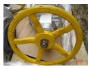 Hand Wheel: It is the most common means of rotating the stem on the majority of popular smaller valves such as gate, globe and diaphragm. Additional operating torque for gate and globe valves is offered by hammer blow or impact hand wheels which may be substituted for normal hand wheels, if easier operation is needed but where gearing is unnecessary.
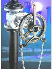 Chain: It is used where a hand wheel would be out of reach. The stem is fitted with a chain wheel or wrench (for lever operated valves) and loop of the chain is brought within one meter of working floor level. Universal type chain wheels which attach the regular hand wheel have been blamed for accidents, in corrosive atmospheres, where an infrequently operated valve has stuck, the attaching bolts have been known to fail. This problem does not arise with the chain-wheel that replaces the regular valve hand-wheel.
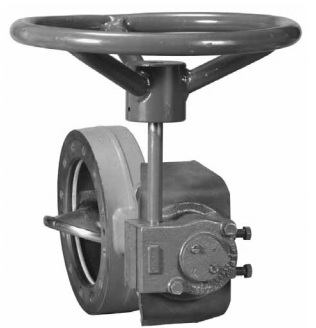 Gear: These are used to reduce the operating torque. For manual operation, it consists of a hand wheel operated gear train actuating the valve stem. As a guide, gear operators should be considered for valves of 350 mm NB and larger up to 300#, 200 mm NB and larger up to 600#, 150 mm NB and larger up to 1500# and 100 mm NB and larger for higher ratings.
- Powered Operators
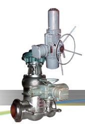 Electric Geared Motor: The valve stem is moved by Geared Motor. This is useful for operating large valves in remote areas.
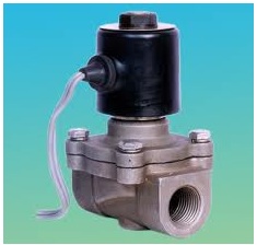 Solenoid: These can be used for fast acting check valves, and with on/off valves in light-duty instrumentation applications.
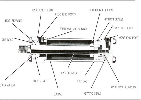 Pneumatic and Hydraulic: These may be used where flammable vapor is likely to be present. They are of following forms:
Cylinder with double acting piston, driven by air, water, oil or other liquids, which usually actuates the stem directly.
Air motor which actuates the stem through gearing. Commonly these motors are piston type and radial cylinder type.
A double acting vane with limited rotary movement in a sector casing, which actuates the stem directly.
- Squeeze type.
Gate Valve: There are different types of gate valves.
Plug Gate Valves: This valve has round tapered disc which moves up and down. Suitable for throttling and full flow use, but only available in smaller sizes.
Single Disc Parallel Seat Gate Valve: Unlike single seat valve described above, this valve affords closure with flow in either direction. Stresses on stem and bonnet are lower than wedge gate valves. It is primarily used for liquid hydrocarbons and gases.
Single Disc Single Seat Gate Valve or Slide Valve: It is used for handling paper and pulp slurry and other fibrous suspensions, and for low pressure gases. It will not function properly with inflow on the seat side. It is suitable for regulating if tight closure is not required.
Double Disc (Split Wedge) Gate Valve: In this the discs wedge against inclined seats without use of a spreader. Other features are same as parallel seat. It allows the disc to rotate, distributing wear.
Double Disc Parallel Seat Gate Valve: It has two parallel discs which are forced on closure, against parallel seats by a spreader. It is used for liquids and gases at normal temperatures. It is not suitable for regulation. To prevent jamming, it is installed vertically.
Solid Wedge Gate Valve: It has either solid or flexible wedge disc. In addition to on/off service, these valves can be used for regulating usually in sizes of 150 mm NB and larger, but it will make noise unless disc is fully guided throughout travel. Suitable for most liquids and gases.
| Size NB | Length | Diameter | Flange Thickness | Handle Dia | Height |
| 40 | 165 | 127 | 14.3 | 152 | 330 |
| 50 | 178 | 152.5 | 16 | 203 | 360 |
| 65 | 190.5 | 178 | 17.5 | 203 | 415 |
| 80 | 203 | 190.5 | 19 | 254 | 425 |
| 100 | 229 | 229 | 24 | 254 | 510 |
| 125 | 254 | 254 | 24 | 305 | 595 |
| 150 | 267 | 279.5 | 25.4 | 305 | 685 |
| 200 | 292 | 343 | 28.6 | 305 | 773 |
| 250 | 330 | 406.5 | 30.5 | 408 | 940 |
| 300 | 356 | 483 | 32 | 457 | 1030 |
| 350 | 381 | 533.5 | 36 | 457 | 1270 |
| 400 | 406.5 | 597 | 36.5 | 508 | 1450 |
| 450 | 432 | 635 | 40 | 508 | 1600 |
| 500 | 457 | 698.5 | 43 | 610 | 1810 |
| 600 | 508 | 813 | 48 | 610 | 2170 |
MATERIALS OF CONSTRUCTION
| CARBON STEEL STAINLESS STEEL NICKEL ALLOY |
- MANUFACTURING STANDARDS: BS:1414/API-600/API-6D/ANSI B-16.34
- FACE TO FACE AS PER ANSI B 16.10
- ENDS FLANGED & DRILLED AS PER ANSI B 16.5 RF
- TESTED AS PER BS:5146, API 598
- AVAILABLE IN CLASS 900, 1500
- AVAILABLE WITH ACTUATOR OPERATOR
- AVAILABLE WITH EXTENSION STEM
| Test Pressure Kg/cm2 | |||
| Class | Hydrostatic | Air | |
| Body | Seat & Back Seat | Seat | |
| 150 | 30 | 22 | 6 |
| 300 | 76 | 55 | 6 |
| 600 | 150 | 110 | 6 |
Sizes of 300# Gate Valves
| Size NB | Length | Diameter | Flange Thickness | Handle Dia | Height |
| 40 | 190.5 | 156 | 21 | 152 | 390 |
| 50 | 216 | 165 | 22 | 203 | 370 |
| 65 | 241.5 | 190.5 | 25.4 | 203 | 440 |
| 80 | 282.5 | 210 | 29 | 254 | 445 |
| 100 | 305 | 254 | 32 | 254 | 520 |
| 125 | 381 | 279.5 | 35 | 305 | 570 |
| 150 | 403.5 | 317.5 | 36.5 | 356 | 740 |
| 200 | 419 | 381 | 41.6 | 406 | 910 |
| 250 | 457.5 | 444.5 | 48 | 458 | 1100 |
| 300 | 502 | 521 | 51 | 508 | 1200 |
| 350 | 762 | 584.5 | 54 | 559 | 1415 |
| 400 | 838.5 | 648 | 57.5 | 610 | 1540 |
| 450 | 914.5 | 711.5 | 60.5 | 813 | 1670 |
| 500 | 991 | 775 | 63.5 | 965 | 1910 |
| 600 | 1143 | 914.5 | 70 | 1508 | Gear |
| Size NB | Length | Diameter | Flange Thickness | Handle Dia | Height |
| 40 | 241.5 | 156 | 28.6 | 203 | 380 |
| 50 | 292 | 165 | 32 | 203 | 445 |
| 65 | 330 | 190.5 | 35 | 254 | 475 |
| 80 | 356 | 210 | 38 | 254 | 490 |
| 100 | 432 | 273 | 44.5 | 305 | 615 |
| 125 | 508 | 330.5 | 51 | 406 | 765 |
| 150 | 559 | 356 | 54 | 457 | 840 |
| 200 | 660.5 | 419 | 62 | 508 | 950 |
| 250 | 787.5 | 508 | 70 | 610 | 1290 |
| 300 | 838.5 | 559 | 73 | 406 | Gear |
| 350 | 889 | 603.5 | 76.5 | 508 | Gear |
| 400 | 991 | 686 | 82.5 | 508 | Gear |
| 450 | 1093 | 743 | 89 | 508 | Gear |
| 500 | 1194 | 813 | 95.5 | 508 | Gear |
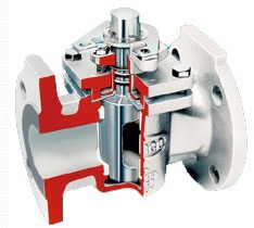 Plug Valve: It has a cylindrical or tapered plug in the body. Its advantage is that it is compact and a quarter turn valve. The tapered plug tends to jam and requires high operating torque. This is overcome to some extent by low-friction teflon seat or by lubrication (with the drawback that it may contaminate the conveyed fluid). It is mainly used for water, oil, slurries or gases as quick closing valve.
Globe Valve: There are different types of Globe Valves.

 Blow Off Valve: It confirms to boiler codes. Y and angle types are often used. It is used to remove air and other gases from boilers. It is manually operated.
Double Disc Globe Valve: It features two discs bearing on separate seats spaced apart on a single shaft, which frees the operator from stresses set up by the conveyed fluid pressing into the valve. It is principally used on control valves and pressure regulators for steam and other gases. Tight shut-off is not possible.
Composition Disc Globe Valve: It is suitable for coarse regulation and tight shut off. Replacable composition disc construction is similar to that of a faucet. Grit will imbed in the soft disc preventing seat damage and ensuring good closure. Close regulating will rapidly damage the seat.
Wye Body Globe Valve: It has in-line ports and stem emerging at about 45o, hence the name Y. It is preferred for erosive fluids due to smoother flow patterns.
Plug Type Disc Globe Valve: It is used for severe regulating service with gritty liquids, such as boiler feed water, and for blow-off service. It is less subjected to wear under close regulation than the regular seated valve.
Regular Disc Globe Valve: This is unsuitable for close regulation as disc and seat have narrow (almost line) contact.
Angle Valve: This is globe valve with body ends at right angles, saving the use of a 90o elbow. However, higher stress may prevent its use.
Straight Globe Valve: These are used for regulating service. For line sizes over 150 mm NB, choice for flow control may go for gate or butterfly valve. The direction of flow around disc is in upward direction.
| Size NB | Length | Diameter | Flange Thickness | Handle Dia | Height |
| 25 | 127 | 108 | 11.1 | 152 | 260 |
| 40 | 165 | 127 | 14.3 | 152 | 300 |
| 50 | 203 | 152.5 | 16 | 203 | 330 |
| 65 | 216 | 178 | 17.5 | 203 | 334 |
| 80 | 241.5 | 190.5 | 19 | 254 | 395 |
| 100 | 292 | 229 | 24 | 305 | 470 |
| 125 | 356 | 254 | 24 | 305 | 510 |
| 150 | 406.5 | 279.5 | 25.4 | 356 | 570 |
| 200 | 495.5 | 343 | 28.6 | 406 | 642 |
| 250 | 622.5 | 406.5 | 30.5 | 406 | 768 |
| 300 | 698.5 | 483 | 32 | 508 | 770 |
| 350 | 787.5 | 533.5 | 35 | 508 | 920 |
| 400 | 914.5 | 597 | 36.5 | 508 | 1010 |
| 450 | 978 | 635 | 40 | 559 | 1062 |
| 500 | 978 | 698.5 | 43 | 559 | 1220 |
| Size NB | Length | Diameter | Flange Thickness | Handle Dia | Height |
| 25 | 203 | 124 | 17.5 | 152 | 295 |
| 40 | 229 | 156 | 21 | 203 | 310 |
| 50 | 267 | 165 | 22.2 | 203 | 325 |
| 65 | 292 | 190.5 | 25.4 | 254 | 330 |
| 80 | 317.5 | 210 | 28.6 | 254 | 450 |
| 100 | 356 | 254 | 32 | 305 | 515 |
| 125 | 400 | 279.5 | 35 | 356 | 530 |
| 150 | 444.5 | 317.5 | 36.5 | 356 | 600 |
| 200 | 559 | 381 | 41.5 | 356 | 730 |
| 250 | 622.5 | 444.5 | 48 | 406 | 840 |
| 300 | 711.5 | 521 | 51 | 508 | 1005 |
| Size NB | Length | Diameter | Flange Thickness | Handle Dia | Height |
| 25 | 216 | 124 | 24 | 152 | 295 |
| 40 | 241.5 | 156 | 28.6 | 203 | 310 |
| 50 | 292 | 165 | 32 | 203 | 325 |
| 65 | 330 | 190.5 | 35 | 254 | 381 |
| 80 | 356 | 210 | 38 | 254 | 485 |
| 100 | 432 | 273 | 44.5 | 305 | 623 |
| 125 | 508 | 330.5 | 51 | 356 | 660 |
| 150 | 559 | 356 | 54 | 356 | 778 |
| 200 | 660.5 | 419 | 62 | 406 | 828 |
| 250 | 787.5 | 508 | 70 | 508 | 942 |
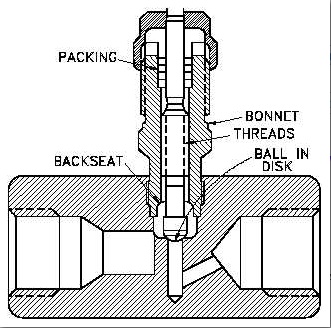 Needle Valve: It is small valve used for flow control and for dosing liquids and gases. Resistance to flow is precisely controlled by a relatively larger seat area and the adjustment afforded by fine threading of the stem.
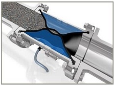 Squeeze Valve: It is well suited to regulating the flow of difficult liquids, slurries and powders. Maximum closure is about 80%, which limits the range of regulation, unless the variation of this type of valve with a central core (seat) is used, offering full closure.
Pinch Valve: It is also suited to regulating flow of difficult liquids, slurries and powders. Complete closure is possible, but tends to rapidly wear the flexible tube, unless it is of special design.
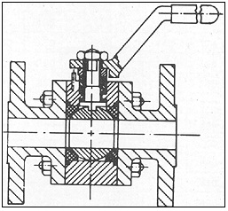 Ball Valve: Its advantages are low operating torque, availability in large sizes, rotary 90o stem movement, compactness, and in-line ability to replace of all wearing parts in some designs. Possible disadvantages are that liquid is trapped within the body (and within the ball on closure), and that compensation of wear is affected only by resilient material behind the seats. The later is avoided in single seat eccentric version, which has the ball slightly offset so that it presses into the seat, on closure. Principal uses are for water, oil, slurries, gases and vacuum. Valve is available with a ball having a shaped port for regulation. It can have full port or reduced port.
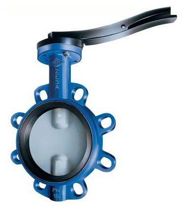 Butterfly Valves: This offers advantage of rotary stem movement (90o or less), compactness and absence of pocketing. It is available in all sizes, and can be produced in chemical-resistant and hygienic forms. The valves are used for gases, liquids, slurries, powders and vacuum. The usual resilient plastic seat has a temperature limitation, but tight closure at high temperatures is available with the version having metal ring seal around the disc. If the valve is flanged, it may be held between flanges of any type. Slip-on and screwed flanges do not form a proper seal with some wafer types of the valve, in which the resilient seat is extended to serve also as line gaskets.
Check Valve: There are different types of check valves.
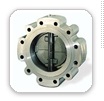 Wafer Check Valve: It effects closures by two semi-circular doors, both hinged to a central post in a ring-shaped body which is installed between flanges. It is frequently used for non-fouling liquids, as it is compact and relatively low cost. A single disc type is also available.
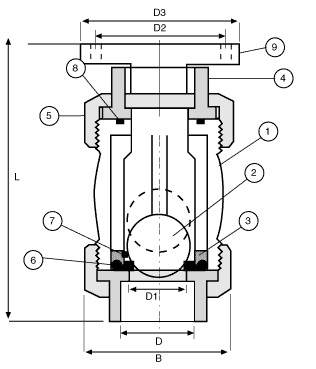 Ball Check Valve: It is suitable for most services. The valve can handle gases, vapors and liquids, including those forming gummy deposits. The ball sits by gravity and / or back pressure, and is free to rotate, which distributes wear and aids in keeping contacting surfaces clean.
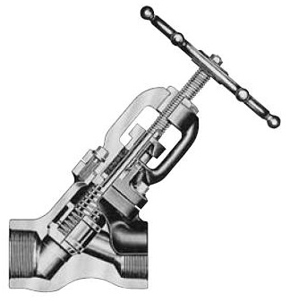 Stop Check Valve: Its principal use is in steam lines, with steam generation by multiple boilers. It can be kept closed automatically or manually.
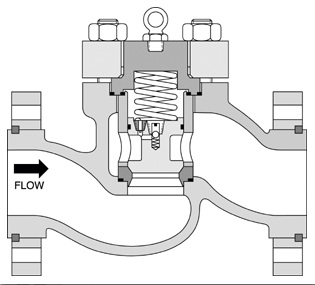 Piston Check Valve: It changes the flow in 90o, and it also has a lifting disc. It has less pounding with frequent changes in flow direction. Spring loaded can operate in any orientation. It is not suitable for gritty liquids.
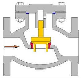 Lift Check Valve: In this the disc is guided and it rises upward with fluid pressure, and closes by gravity. It can be installed horizontally or vertically if spring is provided to push the disc back.
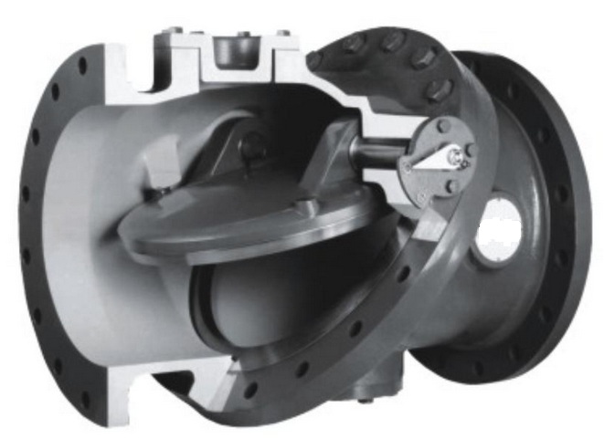 Tilting Disc Valve: It is suitable where frequent flow reversal occurs. Valve closes rapidly with better closure and less slamming than the swing check valve, which it somewhat resembles. It can be installed vertically with upward flow or horizontally.
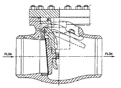 Swing Check Valve: The regular swing check valve is not suitable if there is frequent flow reversal as pounding and wearing of disc occurs. For gritty liquids, a composition disc is advisable to reduce damage to the seat. It may be mounted vertically with upward flow or horizontally.
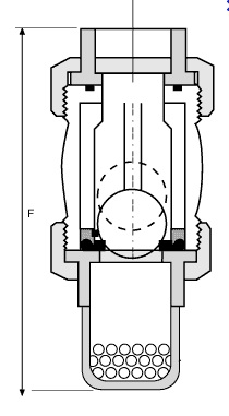 Foot Valve: It is typically used to maintain a column of water on suction side of a pump. The valve is basically a lift-check valve with an integrated strainer.
Sizes of 150# Check Valves
| Size NB | Length | Diameter | Flange Thickness | Height |
| 40 | 165 | 127 | 14.3 | 112 |
| 50 | 203 | 152.5 | 16 | 138 |
| 65 | 216 | 178 | 17.5 | 160 |
| 80 | 241.5 | 190.5 | 19 | 170 |
| 100 | 292 | 229 | 24 | 185 |
| 125 | 330 | 254 | 24 | 215 |
| 150 | 356 | 279.5 | 25.4 | 245 |
| 200 | 495.5 | 343 | 28.6 | 305 |
| 250 | 622.5 | 406.5 | 30.5 | 340 |
| 300 | 698.5 | 483 | 32 | 400 |
| 350 | 787.5 | 533.5 | 36 | 450 |
| 400 | 864 | 597 | 36.5 | 470 |
| 450 | 978 | 635 | 40 | 525 |
| 500 | 978 | 698.5 | 43 | 559 |
| 600 | 1296 | 813 | 48 | 650 |
Sizes of 300# Check Valves
| Size NB | Length | Diameter | Flange Thickness | Height |
| 40 | 241.5 | 155.5 | 21 | 140 |
| 50 | 267 | 165 | 22.5 | 160 |
| 65 | 292 | 190.5 | 25.4 | 180 |
| 80 | 317.5 | 210 | 29 | 200 |
| 100 | 356 | 254 | 32 | 225 |
| 125 | 400 | 279.5 | 35 | 250 |
| 150 | 444.5 | 317.5 | 36.5 | 265 |
| 200 | 533.5 | 381 | 41.5 | 325 |
| 250 | 622.5 | 444.5 | 48 | 390 |
| 300 | 711.5 | 521 | 51 | 465 |
| 350 | 838.5 | 584.5 | 54 | 470 |
| 400 | 864 | 648 | 57.5 | 500 |
| 450 | 978 | 711.5 | 60.5 | 580 |
| 500 | 1016 | 775 | 63.5 | 675 |
| 600 | 1346 | 914.5 | 70 | 775 |
Sizes of 600# Check Valves
| Size NB | Length | Diameter | Flange Thickness | Height |
| 40 | 241.5 | 155.5 | 28.6 | 160 |
| 50 | 292 | 165 | 32 | 170 |
| 65 | 330 | 190.5 | 35 | 190 |
| 80 | 356 | 210 | 38 | 200 |
| 100 | 432 | 273 | 44.5 | 235 |
| 125 | 508 | 330.5 | 51 | 285 |
| 150 | 559 | 356 | 54 | 325 |
| 200 | 660.5 | 419 | 62 | 425 |
| 250 | 787.5 | 508 | 70 | 500 |
| 300 | 838.5 | 559 | 73 | 500 |
| 350 | 889 | 603.5 | 76.5 | 590 |
| 400 | 991 | 686 | 82.5 | 655 |
| 450 | 1092.5 | 743 | 89 | 680 |
| 500 | 1194 | 813 | 95.5 | 785 |
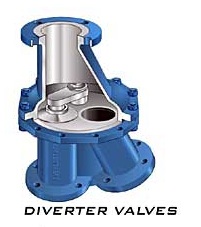 Diverting Valves: Two types of diverting valves are made. Both switch flow from a line into one of two outlets. One type is of Y pattern has a hinged disc at the junction which closes one of the two outlets, and is used to handle powders and other solids. The second type handles liquids only, and has no moving parts. Flow is switched by two pneumatic control lines. It is available up to 150 mm NB.
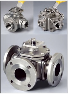 Multi Port Valves: It is used largely on hydraulic and pneumatic control circuits and sometimes used directly in process piping. These valves have rotary ball or plug type discs with one or more ports arranged to switch flow.
Safety Valve: There are different types of safety valves.
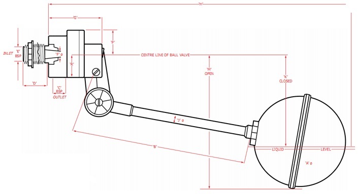 Ball Float Valve: These automatic valves are used in steam traps to remove condensate water from the system, to remove air from liquid systems and as vacuum breaker or breather valves. It is widely used to control liquid level in Cooling Water tank.
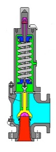 Safety Relief Valve (Temperature Safety Valve): It relives excess pressure of either gas or liquid which may suddenly develop a vapor phase due to rapid and uncontrolled heating from chemical reaction in liquid-laden vessels. It lifts up due to sudden change in temperature in the valve.
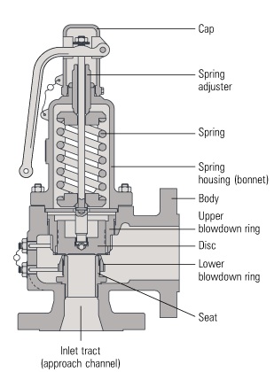 Relief Valve: It is used to relieve excess pressure in liquids or steam, in situations, where full flow discharge is not required, when release of small volume of liquid would rapidly lower pressure. It is mounted vertically. Its outlet is of bigger size than inlet because volumn of fluid in outlet is much higher than inlet, due to reduction in pressure.
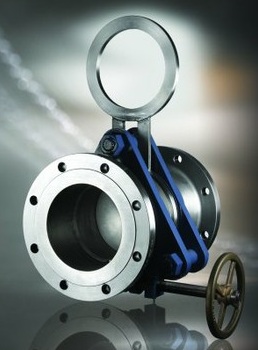 Line Blind Valve: This is a positive shut-off device which basically consists of a flanged assembly, sandwitching a spectacle plate or blind. It is used where spectacle blind needs to be installed and removed frequently.
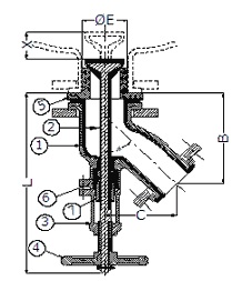 Flush Bottom Valve: It is usually installed on the bottom of the tanks and vessels. These are usually globe type valves, designed to minimize pocketing, primarily for convenient discharging of liquids with suspended solids in it from the low point of a tank. The regulating part is like inverted bucket and it sits deep in the bottom nozzle. It goes into the vessel, when opened. It is used for slurry material in the vessel.
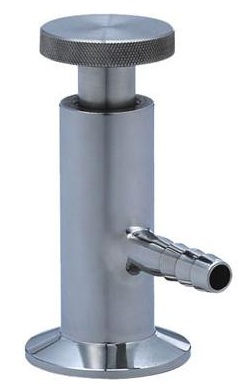 Sampling Valve: A valve usually of needle or globe pattern, placed in a branch line for the purpose of drawing off samples of process materials through a branch. Sampling from very high pressure lines is best done through a double valved collecting vessel. A cooling arrangement may be needed for sampling from high temperature lines.
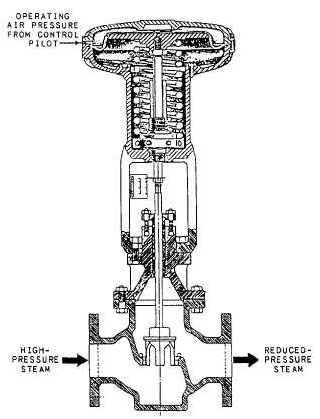 Control Valve: It automatically regulates pressure and / or flow rate, and are available for any pressure. If there are different system pressures, in a plant up to and including 300#, sometimes all control valves chosen will be rated at 300# for inter-changability. The size of control valve is usually chosen to be smaller than size of the pipe line, to avoid throttling and consequent rapid wear of the seat. Globe pattern valves are normally used for control, and their ends are usually flanged for ease of maintenance. The disc is moved by hydraulic, pneumatic, electrical or mechanical actuator.
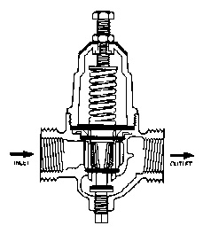 Pressure Regulating Valve: These are control valves of globe type, which adjust downstream pressure of liquid or gas (including steam or vapor) to a lower desired value called set pressure.
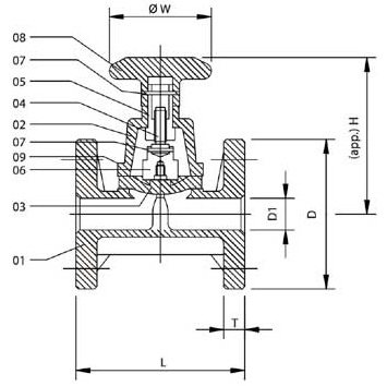 Diaphragm Valve: It is used for regulating flow of slurries and corrosive liquids and for vacuum. The term diaphragm valve is also applied to valves which have a diaphragm seal between stem and body.
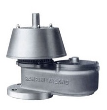 Breather Valve: A special self acting valve installed on storage tanks, long distance pipe lines etc., to release air or gas accumulated inside.
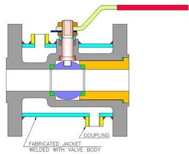 Jacketed Valve: The jacket covers the body from one flange to the other flange. The body is modified by adding oversize flanges. As example: 2" x 3" Jacketed Ball Valve has the nominal bore of 2" (DN 50) and the flange size is 3"(DN 80). It allows enough space for bolting clearance. The Jackets assure consistent valve Heating or Cooling of the process media to prevent crystallization or seizing of flow media. The Jacketed Ball Valve (Heating Jacket Ball Valve) with very well design to help the high temperature steam or oil flow over the valve ball & body parts to keep the media liquid. This applies especially to media like bitumen and liquid sulfur. In addition, the efficient flow of media is ensured through the elimination of pockets.
Steam, can be used as heating media. Following quality assurance rules, every valve is tested again after the Jackets have been welded (Fabricated) to the body. Jacket Hydraulic & Air Test is carried out at 6.0 Kg / cm2.
Generally standard Jacketed Ball Valves are delivered in carbon steel and different types of stainless steel materials. Other special materials are also available upon special request. Jacketed P.T.F.E. seated Ball Valves gives Zero Leakage, Tight Shut-Off and Low Torque with easy and smooth operation at temperature ranging from -20oC. to +220oC. Electro-Polished, Buff Finish & Ultra clean valve, are also provided for Food & Pharmaceutical Industries on request.