 |
 |
Satish Lele leleequip@gmail.com |
I offer a Drawing program which Draws a detailed drawing of Components of a Chemical Process Vessel, with user friendly dialog boxes, which is an add-on for any CAD program. It is useful for adding components to GA drawing of a Chemical Process Vessel. The Program asks for some parameters and draws the Components. Program for Drawing of Chemical Process Vessel draws the GA drawing and components.
To run the program, unzip particular zip and copy files in one folder on hard disk (and not on desk top), say vessel. While running in CAD program click on tools ->Options (or Preferences) -> Files -> + of Support File Search Path -> Add -> Browse -> Select the folder (vessel), and click on apply. Use APPLOAD command to load the program. Program will be loaded. Command line will indicate how to start program.
The drawing program can be used to draw GA of the vessel. You can draw add-on items like, Shell, Heads, Nozzles, Manhole, Lugs Legs or Saddle, etc. on vessel GA drawing. In most drawings, location of nozzles is not indiated intially but it can be added any time later.
You can draw either in Foot-Inch units or in Metric Units. In Metric system it asks for all values in millimeters and in Foot-inch systems it asks for all values in Foot-inch.
| Programs Available |
| SHELL / JACKET |
| HEAD |
| NOZZLE / SOCKET |
| MANHOLE |
| NOZZLE TABLE |
| SADDLE |
| VIEW GLASS |
| LUG SUPPORTS |
| LEG SUPPORTS |
| BODY FLANGE |
| LIMPET COIL |
| INTERNAL COIL |
| BAFFLES |
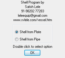
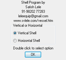
You can draw a shell made from a plate with Jacket or Standard Pipe. You can draw a vertical shell and Jacket or horizontal shell and Jacket.
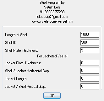
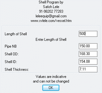
If you select shell from plate option, you well be asked to enter shell length, shell ID and shell thickness. Select on screen. Vessel Top Center point and shell will be drawin with dimensions.
If you select horizontal shell, you well be asked to enter shell length, shell ID and shell thickness. Select on screen. Vessel Left Center point and shell will be drawin with dimensions.
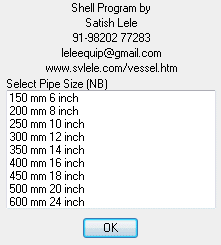 Pipe NB | 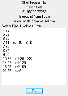 Pipe Thickness |
 |
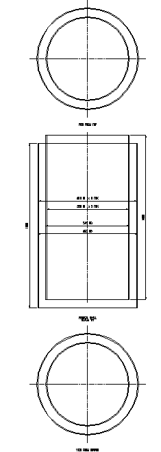 Vertical Shell | 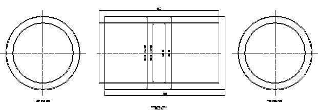 Horizontal Shell |
 to Download Trial Program.
 Program of Drawing of Chemical Process Vessel shell is for sale: Price: US$ 5 OR
  500.
500.As soon as I get the money, I will send Program by Email or whatsapp.
for details.
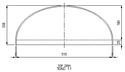
With this you have four options: Top, Bottom, Left or Right. For each of these you can have options: Torispherical Dish, Flat, Conical, Toriconical or Ellipsoidal Head. You can draw in Metric or Foot-Inch units. You can draw it at a scale of 1:1, 2:1 or 3:1 (especially for details).
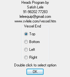
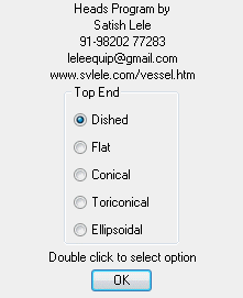
You can draw Top, Bottom, Left or Right Head. For all these heads there are 5 options. Dished end, Flat end, Conical end, Toriconical end and Ellipsoidal end.
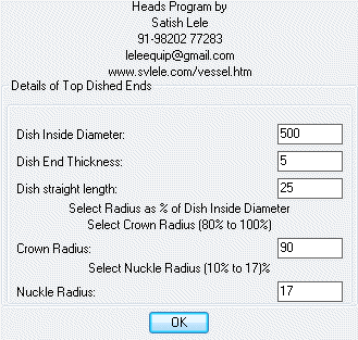
For dished end, in dialog box, enter values of Inside diameter of Dish, Thickness of Dish and Straight Length. You can select a crown radius = 80% to 100% of Inside Diameter of Dish. You can select a nuckle radius = 10% to 17% of Inside Diameter of Dish.
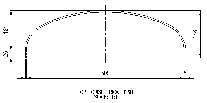
Select the center point of end of vessel, and dish id drawn.
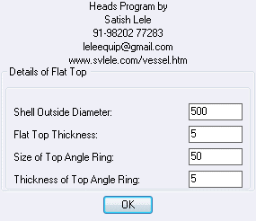
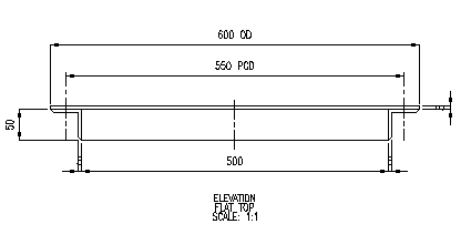
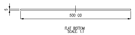
If you select flat Top or Bottom option, select values in dialog box. Select insertion point, and it will be drawn.
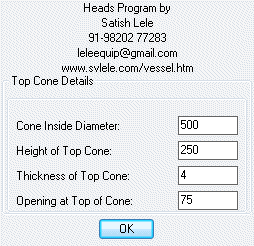
If you select Conical option, select values in dialog box. Select insertion point, and it will be drawn.
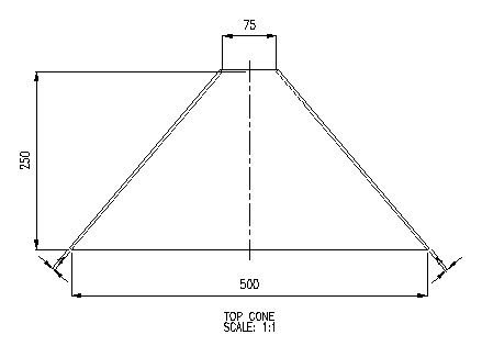
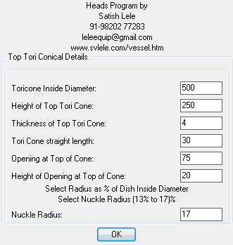
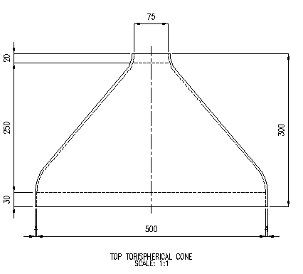
If you select Toriconical option, select values in dialog box. You can select a nuckle radius = 10% to 17% of Inside Diameter of Dish. Select insertion point, and it will be drawn.
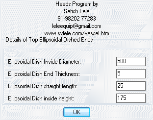
If you select Ellipsoidal option, select values in dialog box.
 to Download Trial Program.Program of Drawing of Chemical Process Vessel shell is for sale: Price: US$ 15 OR 1,500.
As soon as I get the money, I will send Program by Email or whatsapp.
for details.With this you draw nozzles on Shell or Ends. You can draw in Metric or Foot-Inch units.
You can select Nozzle or Socket option
If you select Nozzle option, you can draw Flat View (Elevation or End View). In both the cases, you can draw flanges with American (ASME Standard) or British (BS 10 Standard).
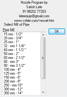
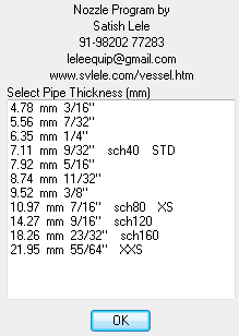
In both the cases, select Pipe NB and Pipe Thickness.
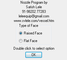
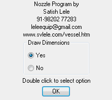
You can select a Raised Face Flange or a Flat Face Flange. Also, you can select, whether to draw Dimensions.
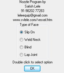
With American (ASME Standard), you draw a nozzle with 4 types of Flanges.
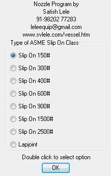
With Slip on Flange option, you select flange of 150#, 300#, 400#, 600#, 900#, 1500# or 2500# rating, as well as Lap Joint Flange.
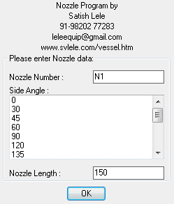
Enter Nozzle Number, Direction Angle of Nozzle and Length of Nozzle.
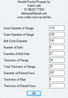
A dialobox will indicate dimension of 100 NB, 150#, Slip on flange as per standard. You can change these values (Not recommended).
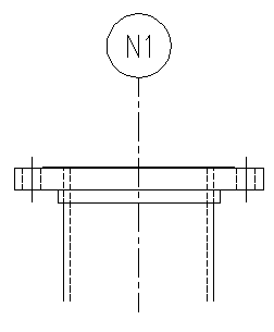
Select insertion point on Shell or End, and nozzle will be drawn.
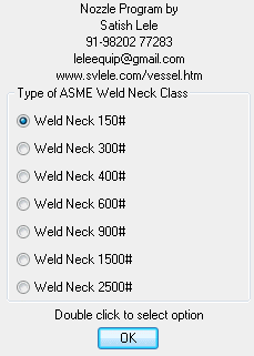
With Weld Neck Flange option, you select flange of 150#, 300#, 400#, 600#, 900#, 1500# or 2500# rating.
Enter Nozzle Number, Direction Angle of Nozzle and Length of Nozzle.
A dialobox will indicate dimension of 100 NB, 150#, Weld neck flange as per standard. You can change these values (Not recommended).
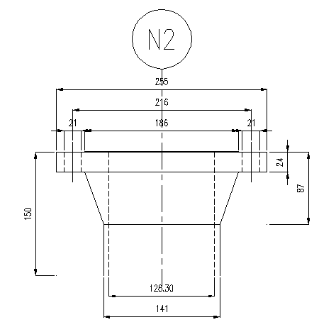
Select insertion point on Shell or End, and nozzle will be drawn.
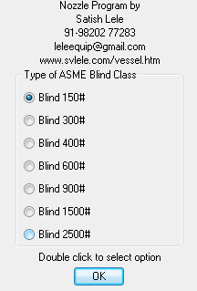
With Blind Flange option, you select flange of 150#, 300#, 400#, 600#, 900#, 1500# or 2500# rating.
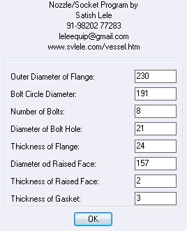
A dialobox will indicate dimension of 100 NB, 150#, Blind flange as per standard. You can change these values (Not recommended)
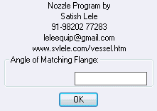
Enter Direction Angle of Matching Flange.
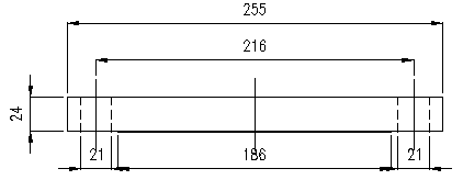
Select center point of Matching Flange, and Blind flange with Gasket, will be drawn.
With Lap Joint Flange option, Enter Nozzle Number, Direction Angle of Nozzle and Length of Nozzle.
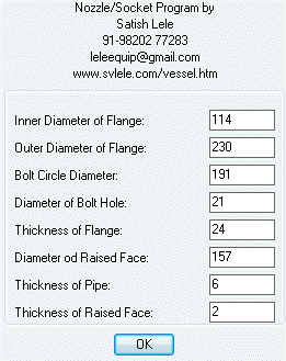
A dialobox will indicate dimension of Lap Joint Flange as per standard. You can change these values (Not recommended)
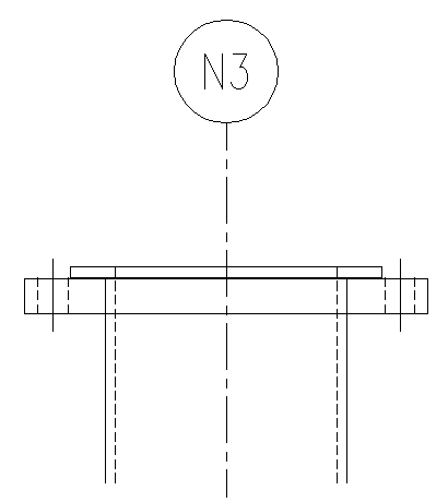
Select insertion point on Shell or End, and nozzle will be drawn.
If you select to draw a nozzle with British (BS 10) Standrd, select Pipe NB and Pipe Thickness. Select Raised face or Flat Face for Flange. Select whether to draw Dimensions.
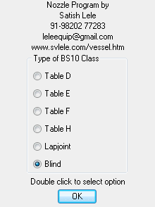
You can draw nozzles with flanges as per Table D, E, F or H. Also you can draw a nozzle with Lap Joint flange, or insert a Blind Flange.
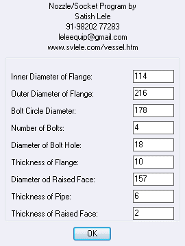
A dialobox will indicate dimension of 100 NB, Table D flange as per standard. You can change these values (Not recommended)
Enter Nozzle Number, Direction Angle of Nozzle and Length of Nozzle.
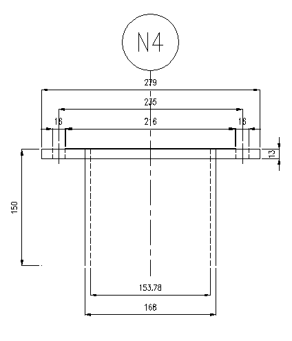
Select insertion point on Shell or End, and nozzle will be drawn.
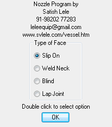
With Circular View, You can select American or British Standrd. Select Pipe NB and Pipe Thickness, Raised Face or Flat Face, whether to draw Dimensions, and select Type of Flange and Class, and Nozzle Number.
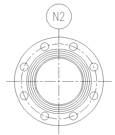
Select center point of Flange, and it will be drawn.
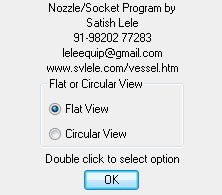
If you select Socket option, you can draw Flat or Circular view of Socket with Plug.
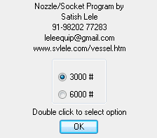
You can select Rating of the Socket.
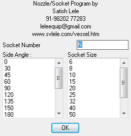
You are requested to enter Socket Number, select side angle of socket and size of socket.
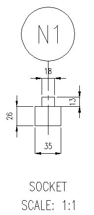
Select center point of flat view of Socket, and it will draw Socket with Plug.
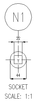
If you select Circular view, it will draw Socket with Plug.
to Download Trial Program.Program of Drawing of Chemical Process Vessel nozzle is for sale: Price: US$ 15 OR 1,500.As soon as I get the money, I will send Program by Email or whatsapp.
for details.With this you draw manhole on Shell or Ends. You can draw in Metric or Foot-Inch units. You can draw it at a scale of 1:1, 2:1 or 3:1 (especially for details). You can draw manhole with or without dimensions. You can draw either OVAL manhole or CIRCULAR manhole. You can draw Elevation or Plan.
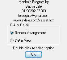
You can draw General Arrangement or Detailed (Exploded) view.
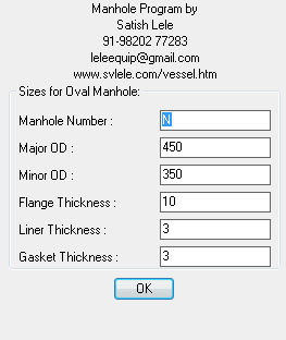
If you select, Oval manhole, enter values in Dialog box.
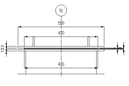
If you have picked up General Arrangement option, pick up center point of manhole on shell or end, and General Arrangement of Manhole will be drawn.
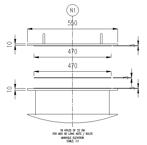
If you have picked up Detailed (Exploded) view option, pick up center point of manhole, and Detailed (Exploded) view of Oval Manhole will be drawn.
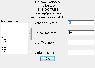
If you select, Circular manhole, enter values in Dialog box.
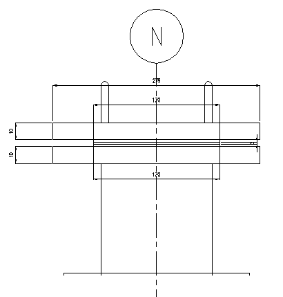
If you have picked up General Arrangement option, pick up center point of manhole on shell or end, and General Arrangement of Circular Manhole will be drawn.
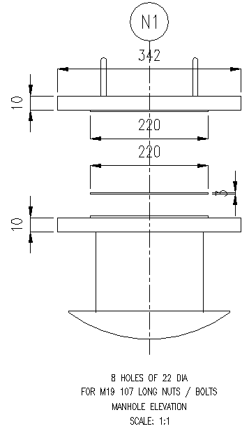
If you have picked up Detailed (Exploded) view option, pick up center point of manhole, and Detailed (Exploded) view of Circular Manhole will be drawn.
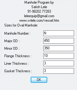
If you select Plan view of Oval Manhole, enter values in Dialog box.
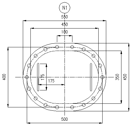
Pick up center point of manhole on shell or end, and Plan of General Arrangement of Manhole will be drawn.
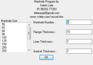
If you select Plan view of Circular Manhole, enter values in Dialog box.
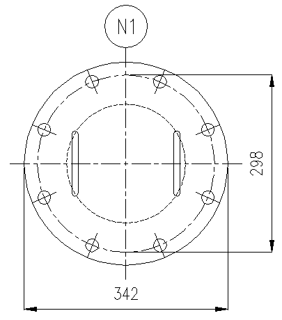
Pick up center point of manhole on shell or end, and Plan of General Arrangement of Manhole will be drawn.
to Download Trial Program.Program of Drawing of Chemical Process Vessel Manhole is for sale: Price: US 5 OR 500.As soon as I get the money, I will send Program by Email or whatsapp.
for details.With this you draw Nozzle Table. You can draw it for drawings in Metric or Foot-Inch units.

Select number of Entries of nozzle. Spare entries can be added later, and spece is provided in nozzle table

Select the right lower corner point of table, where it will be drawn. Once you select the point, you can select the type of nozzle for which information is to be filled. It can be Nozzle, Manhole, Coupling with plug or View Glass.

If you select Nozzle, a dilog box will appear. In this fill appropriate information. Select Pipe Schedule, Flange class, Nozzle DN or NB, Nozzle length, Flange Facing and details of Reinforcing Pad, if it is present. Process will repeat, for number of times of nozzle entries. It directly writes in drawing, at place selected.

If you select Manhole, a dilog box will appear. In this fill appropriate information.

If you select Coupling with plug, a dilog box will appear. In this fill appropriate information.

If you select View Glass, a dilog box will appear. In this fill appropriate information.

Nozzle Table will be drawn at particular location. You can edit the entries using ddedit command.

You can erase some entries and strech the table to remove some columns.
to Download Trial Program.Program of Drawing of Chemical Process Vessel is for sale: Price: US 5 OR 500.As soon as I get the money, I will send Program by Email or whatsapp.
for details.With this you draw saddle for Horizontal Shell. You can draw in Metric or Foot-Inch units.
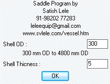
Enter Values in Dialog box.
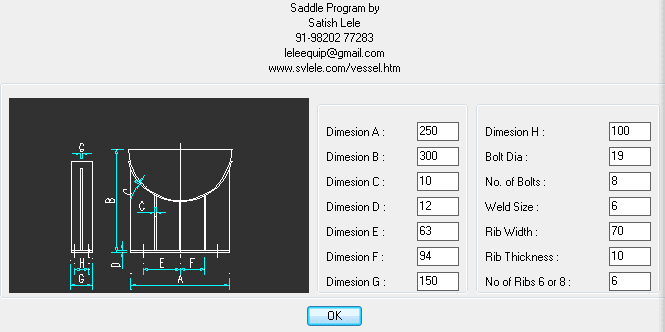
Recommendes sizes will be shwn in Dialog Box. You can change these values.
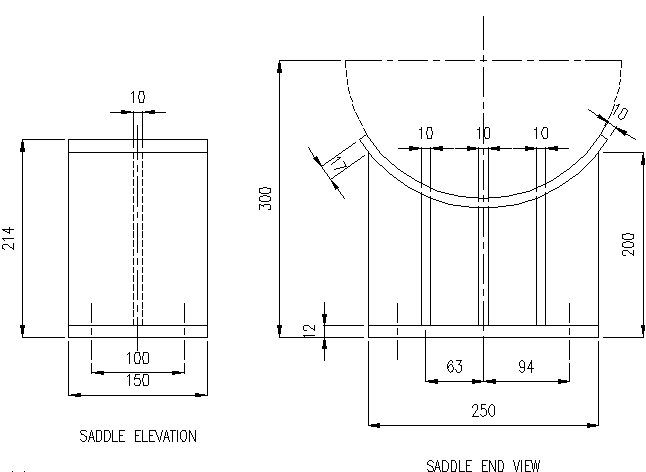
Select center point of saddle, and it will be drawn.
to Download Trial Program.Program of Drawing of Chemical Process Vessel Saddle is for sale: Price: US 5 OR 500.As soon as I get the money, I will send Program by Email or whatsapp.
for details.With this you draw view glass on Shell or Ends. You can draw in Metric or Foot-Inch units. You can draw it at a scale of 1:1, 2:1 or 3:1 (especially for details). You can select, whether to draw Dimensions. You can draw General Arrangement or Detailed (Exploded) view. You can draw either Elevation or Plan view.
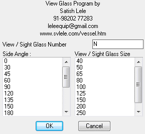
For Elevation view of General Arrangement, select Nozzle Number, Side angle of View Glass and Size of View Glass in Dialog Box.
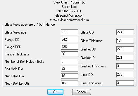
Recommended dimensions, based on size of View Glass will be shown in Dialog Box. You can change these values.
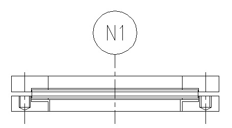
General Arrangement Elevation drawing will be drawn.
For Detailed (Exploded) Elevation view of View Glass, select Nozzle Number, Side angle of View Glass and Size of View Glass in Dialog Box.
Recommended dimensions, based on size of View Glass will be shown in Dialog Box. You can change these values.
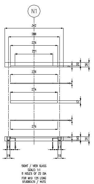
Detailed (Exploded) Elevation drawing will be drawn.
For Plan view of General Arrangement, select Nozzle Number, Side angle of View Glass and Size of View Glass in Dialog Box.
Recommended dimensions, based on size of View Glass will be shown in Dialog Box. You can change these values.
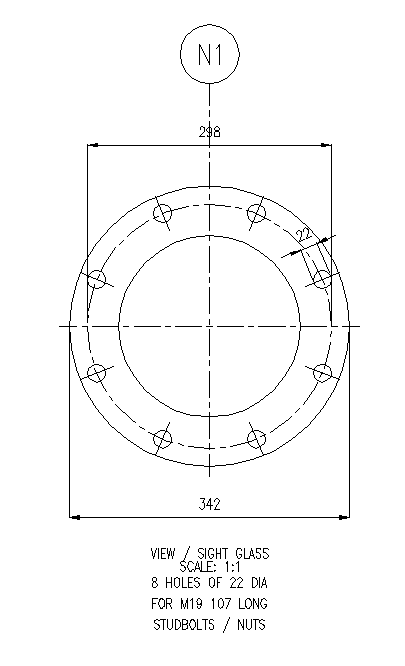
General Arrangement Plan drawing will be drawn.
to Download Trial Program.Program of Drawing of Chemical Process Vessel View Glass is for sale: Price: US 5 OR 500.As soon as I get the money, I will send Program by Email or whatsapp.
for details.With this you draw Lug Supports for a vessel. You can draw in Metric or Foot-Inch units. You can draw it at a scale of 1:1, 2:1 or 3:1 (especially for details). You can select, whether to draw Dimensions. You can draw General Arrangement or Detailed view. You can draw either Elevation or Plan view.
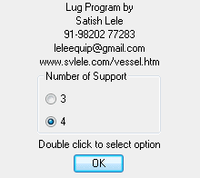
You can select Number of Lug Supports as 3 or 4.
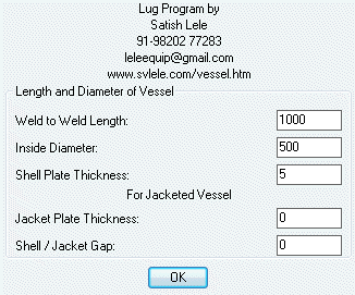
Select Length of Shell, Inside Diameter of shell and Thickness of shell plate. For Jacketed vessel, you can also select Length of Jacket, Inside Diameter of Jacket and Thickness of Jacket plate.
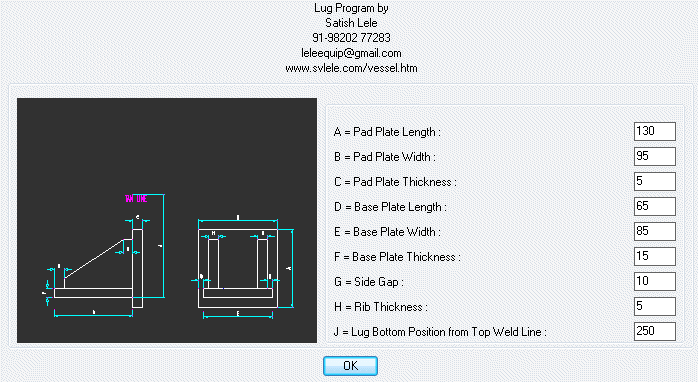
A dialog box will show appropriate dimensions of parts of lug. This is based on weight of vessel and its contents.
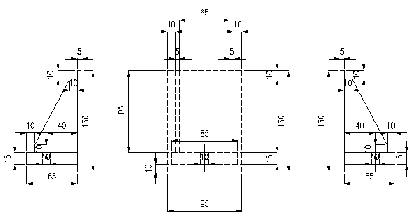
If 4 lugs are selected, in Elevation view, Lugs will be drawn like this on vessel.
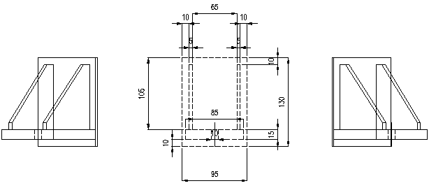
If 3 lugs are selected, in Elevation view, Lugs will be drawn like this on vessel.
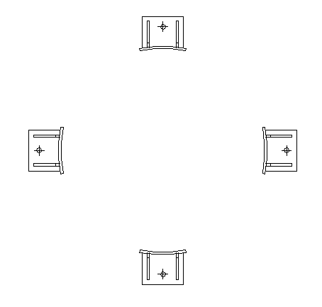
If 4 lugs are selected, in Plan view, Lugs will be drawn like this on vessel.
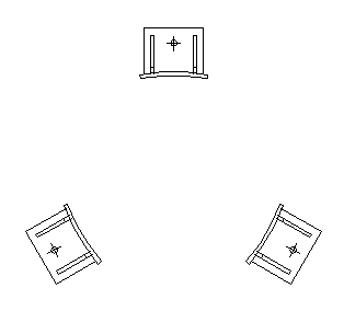
If 3 lugs are selected, in Plan view, Lugs will be drawn like this on vessel.
to Download Trial Program.Program of Drawing of Chemical Process Vessel lug Supports is for sale: Price: US 15 OR 1,500.As soon as I get the money, I will send Program by Email or whatsapp.
for details.With this you draw Leg Supports for a vessel. You can draw in Metric or Foot-Inch units. You can draw it at a scale of 1:1, 2:1 or 3:1 (especially for details). You can select, whether to draw Dimensions. You can draw General Arrangement or Detailed view. You can draw either Elevation or Plan view.
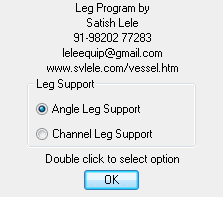
You can select Legs made of Angles or Channels
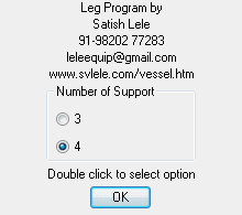
You can select Number of Leg Supports as 3 or 4.
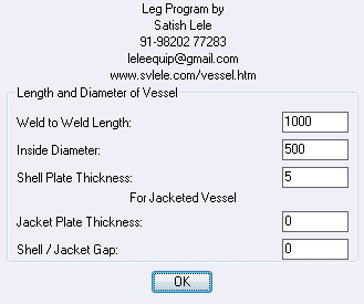
Select Length of Shell, Inside Diameter of shell and Thickness of shell plate. For Jacketed vessel, you can also select Length of Jacket, Inside Diameter of Jacket and Thickness of Jacket plate.
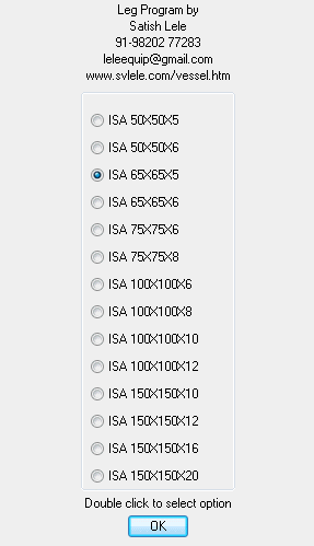
If you select Angle Legs, a Dialog box will indicate appropriate size of Angle required. This will be based on weight of vessel and its contents.
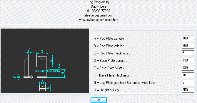
A dialog box will show appropriate dimensions of parts of Angle leg. This is based on weight of vessel and its contents.
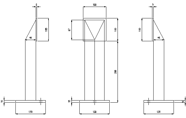
Select center point of middle Leg and if you have selected Elevation view of 4 legs, it will draw legs like this.
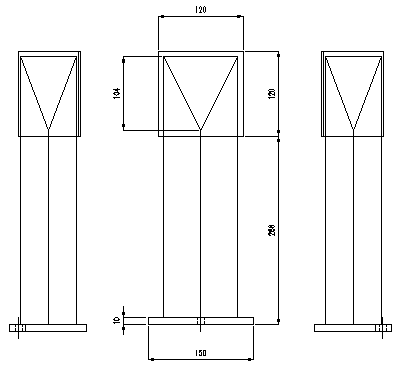
Select center point of middle Leg and if you have selected Elevation view of 3 legs, it will draw legs like this.
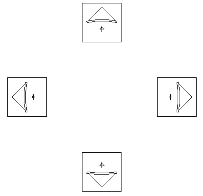
If you select Plan view, of 4 legs, it will draw legs like this.
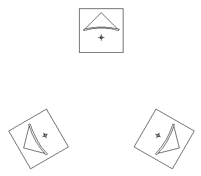
If you select Plan view, of 3 legs, it will draw legs like this.
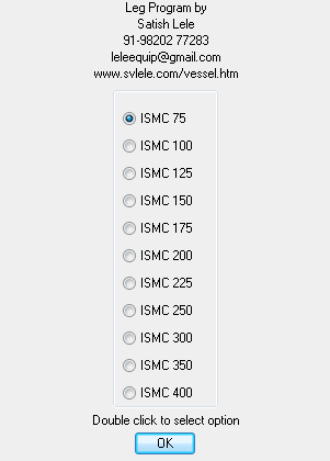
If you select Channel Legs, a Dialog box will indicate appropriate size of Channel required. This will be based on weight of vessel and its contents.
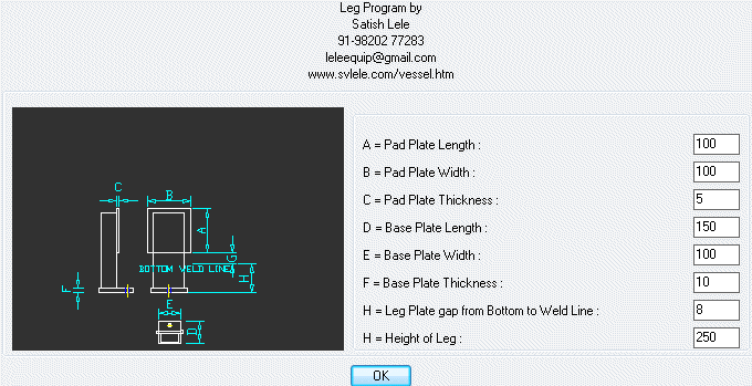
A dialog box will show appropriate dimensions of parts of Channel leg. This is based on weight of vessel and its contents.
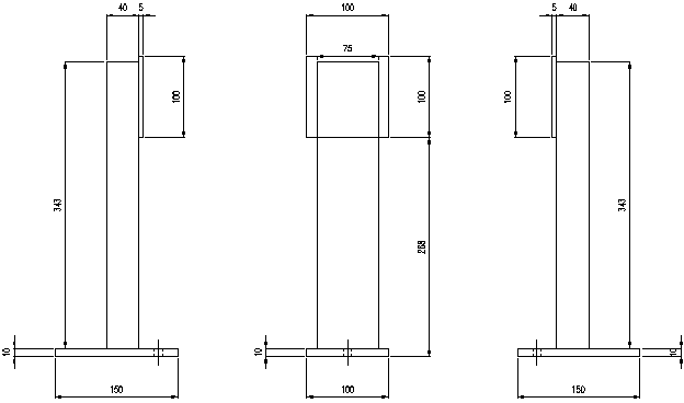
If you have selected Elevation view of 4 Channel legs, Select center point of middle Leg and it will draw legs like this.
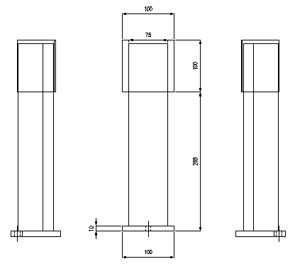
If you have selected Elevation view of 3 Channel legs, Select center point of middle Leg and it will draw legs like this.
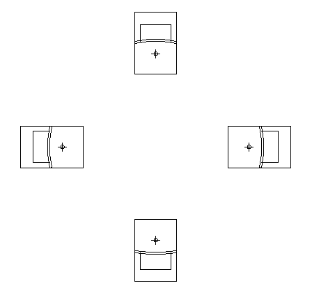
If you select Plan view, of 4 legs, it will draw legs like this.
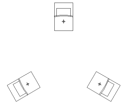
If you select Plan view, of 3 legs, it will draw legs like this.
to Download Trial Program.Program of Drawing of Chemical Process Vessel Leg Supports is for sale: Price: US 15 OR 1,500.As soon as I get the money, I will send Program by Email or whatsapp.
for details.With this you draw Body Flange for a vessel. You can draw in Metric or Foot-Inch units. You can draw it at a scale of 1:1, 2:1 or 3:1 (especially for details). You can draw General Arrangement or Detailed view. You can select, whether to draw Dimensions. You can draw either Elevation or Plan view.
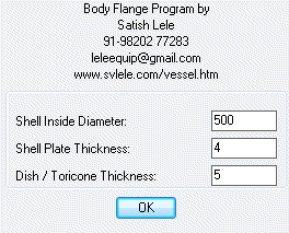
A Dialog box will ask for Shell Inside Diameter, Shell plate thickness and Dish / Toricone thickness.
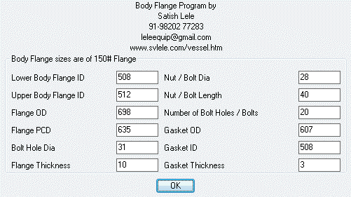
Next dialog box will show appropriate dimentions of Body Flange based on Shell Inside Diameter.
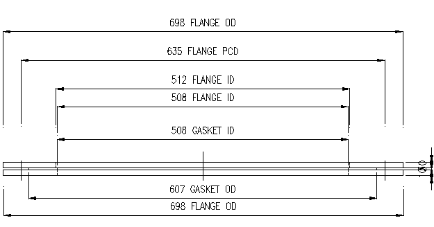
For G A Drawing, select Mid Point of Top Weld Line.
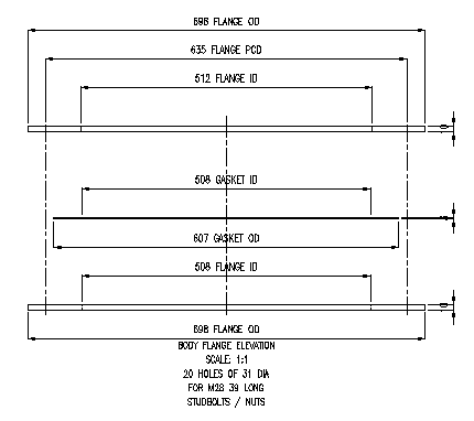
For Detail, select Mid point in detail drawing.
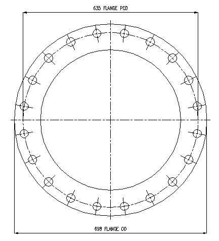
If you select Plan Drawing, it will draw Plan like this
to Download Trial Program.Program of Drawing of Chemical Process Vessel Body Flange is for sale: Price: US 5 OR 500.As soon as I get the money, I will send Program by Email or whatsapp.
for details.With this you draw Limpet coil on Shell. You can draw in Metric or Foot-Inch units. You can draw it at a scale of 1:1, 2:1 or 3:1 (especially for details). You can select, whether to draw Dimensions. You can draw General Arrangement or Detailed view. You can draw either Elevation or Plan view.
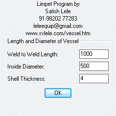
Enter the dimensions of the vessel.
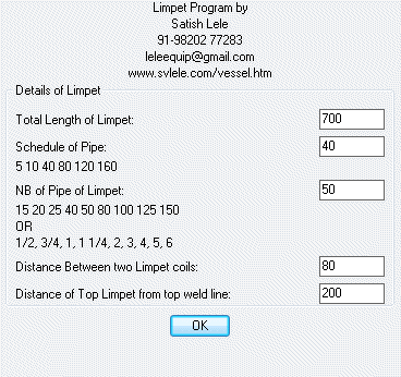
Enter the total length of limpet coil, NB of pipe used for limpet coil, pipe schedule, center to center distance between two limpet coils and distance of first limpet from top weld line.
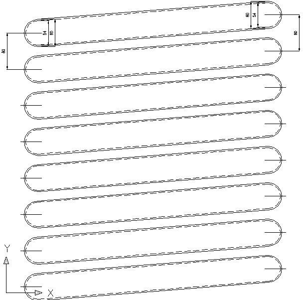
If you select general arrangement of elevation, you get this.
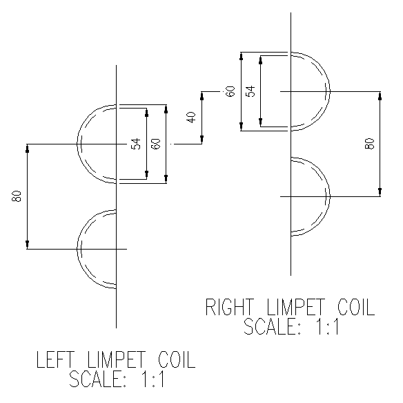
If you select detail view of elevation, you get this.

If you select general arrangement of plan, you get this.
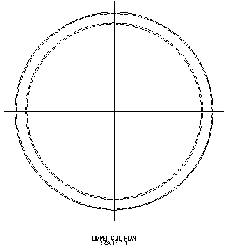
If you select detail view of plan, you get this. It also shows shell with dotted circles.
to Download Trial Program.Program of Drawing of Chemical Process Vessel Limpet coil is for sale: Price: US 5 OR 500.As soon as I get the money, I will send Program by Email or whatsapp.
for details.With this you draw Internal coil. You can draw in Metric or Foot-Inch units. You can draw it at a scale of 1:1, 2:1 or 3:1 (especially for details). You can select, whether to draw Dimensions. You can draw General Arrangement or Detailed view. You can draw either Elevation or Plan view.
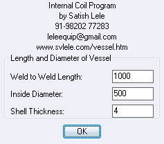
Enter the dimensions of the vessel.
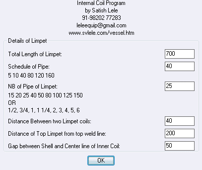
Enter the total length of internal coil, NB of pipe used for internal coil, pipe schedule, center to center distance between two internal coils, distance of first internal from top weld line and gap between shell and center line of internal coil.
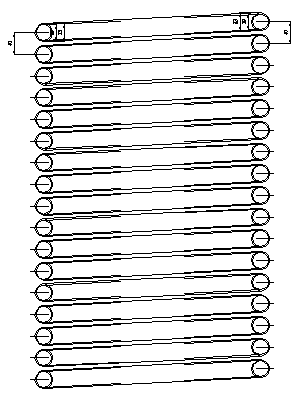
If you select general arrangement of elevation, you get this.
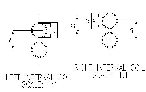
If you select detail view of elevation, you get this.
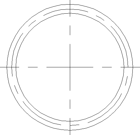
If you select general arrangement of plan, you get this.
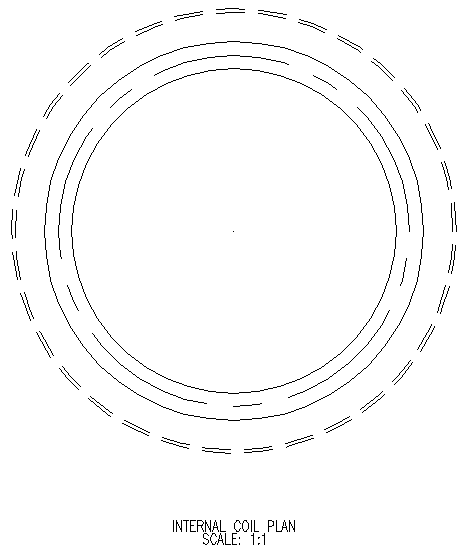
If you select detail view of plan, you get this. It also shows shell with dotted circles.
to Download Trial Program.Program of Drawing of Chemical Process Vessel Limpet coil is for sale: Price: US 5 OR 500.As soon as I get the money, I will send Program by Email or whatsapp.
for details.With this you draw Baffles in a Cricular Vessel. You can draw in Metric or Foot-Inch units. You can draw it at a scale of 1:1, 2:1 or 3:1 (especially for details). You can select, whether to draw Dimensions. You can draw General Arrangement or Detailed view. You can draw either Elevation or Plan view.
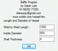
Enter the dimensions of the vessel.
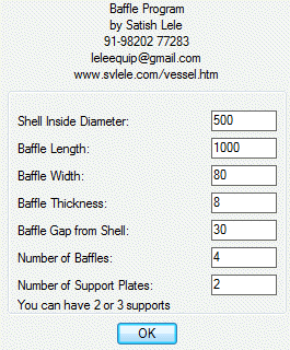
Enter details of baffles.
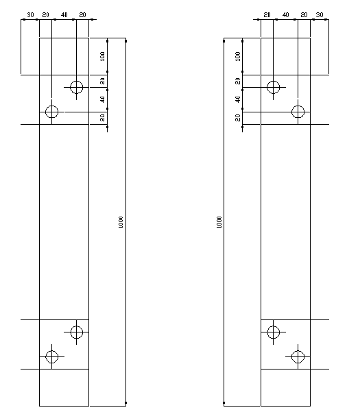
If you select general arrangement, you will get this.
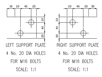
If you select detail view, you will get details of support plates.
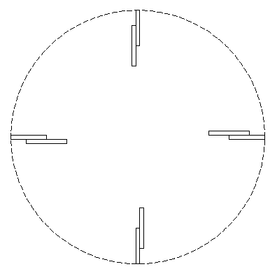
If you select plan view, you will get this.
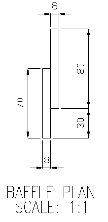
If you select detail view of plan, you will get this
to Download Trial Program.Program of Drawing of Chemical Process Vessel is for sale: Price: US 5 OR 500.As soon as I get the money, I will send Program by Email or whatsapp.
for details. to Download Catalog for Vessel Components Program. Zero Hold up Filter Program Zero Hold up Filter Program |
|
Jib Crane Program |