 |
Satish Lele lelepiping@gmail.com |
This is a program for Skill Development and Bridging the Gap between Manual and Computer work. I offer Training of Basic Fundamentals and How to Use my Software to a batch of 5 to 10 people in your office. This can speed up Drawing work using my own Software, compared to conventional methods. This is a package, which can run on any inexpensive CAD program like BricksCAD, ProgeCAD, IntelliCAD, Draftsight, CADLogic, or ZWCAD program and is very simple and easy to use. |
2D Pipe Routings
Need for 2D Pipe Routings?: To create a 3D Model, first you have to create concenptual 2D Pipe Routing, with pipe center line elevations marked on each horizontal pipe line. This gives idea about layout in plan view. This can be converted in 3D Pipe Routing, by lifting the horizontal pipe lines to the elevations of the pipe center line. In 3D view, the vertical lines can be joined from end points of horizontal pipe lines.
Generaly one pipe line is drawn on one layer. This helps is segragating pipe lines. When one line routing in 3D is completed, that layer can be frozen, to avoid confusion.
Most inexpensive CAD program like BricksCAD, ProgeCAD, IntelliCAD, Draftsight, CADLogic, or ZWCAD Packages are prepared in such a manner that these can be easily customized. 4 Programs of OpenPipe are such customized programs. The 2D program is based totally on LISP programs and no symbols or blocks are created. Pipe line is cut in the portion where fitting is drawn. Since blocks are not there, there is a lot of saving of Disk space. Since the program is written in LISP, program can be even modify further. The different piping entities can be arranged on different layers. This is a menu driven program. Special Dialogue Boxes are created to make the program more user friendly.
| To try the program, send a request for trial package or download from website. The package is a zip file, openpipe.zip. There is no setup.exe file as in other packages. Download and unzip openpipe.zip and copy files in a folder, say openpipe. While running inexpensive CAD program like BricksCAD, ProgeCAD, IntelliCAD, Draftsight, CADLogic, or ZWCAD program, click on tools ->Options (or at command prompt, type _Preferences) -> Files -> + of Support File Search Path -> Add -> Browse -> Select the folder. Click on Apply and the click on close. At command prompt, open trial.dwg and type (load "2p") and press enter. pipe2d will be loaded, and start program by typing 2p. |
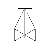
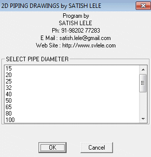
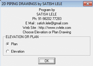
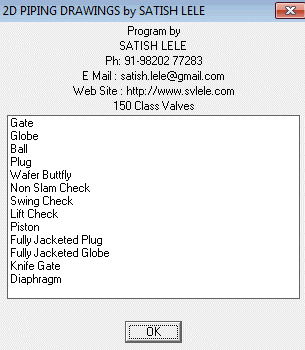
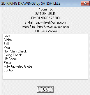
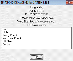
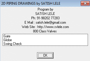
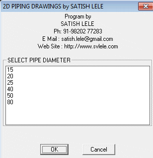
2D Pipe Lines: To draw 2D Pipe routing, first create a Single Line layout. Put each line on a layer having layer name as line number. Then insert pipe fittings. Valves: You can draw 150#, 300#, 600# and 800# Gate, Globe, Check, Wafer Check, Ball, Butterfly and control valves with this. Select Pipe Dia from dialog box. Select on pipeline, the center point of flange and a point in the direction of the valve. Select whether you want to draw valve as Elevation or Plan. A valve will be drawn and pipe will be cut. Sight Glass: You can draw sight glass with Double Window or Full View with this. Select Pipe Dia from dialog box. Select on pipeline, the center point of flange and a point in the direction of the sight glass. A Sight Glass will be drawn and pipe will be cut. Steam Trap: You can draw Steam Trap of Ball Float or Thermodynamic type with this. Select Pipe Dia from dialog box. Select on pipeline, the center point of flange and a point in the direction of the Steam Trap. A Steam Trap will be drawn and pipe will be cut. Strainer: You can draw Line Strainer of Y type (flanged), Y type (socket welded), Y type (screwed) or Basket type with this. Select Pipe Dia from dialog box. Select on pipeline, the center point of flange and a point in the direction of the Strainer. A Strainer will be drawn and pipe will be cut. Elbows: You can draw: Tees: You can draw: Reducers: You can draw:
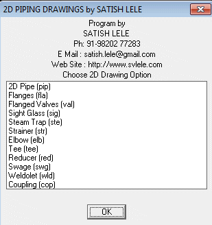 2D Piping Program: This has 12 options. "2D Pipe (pip)" "Flanges (fla)" "Valves (val)" "Sight Glass (sig)" "Steam Trap (ste)" "Strainer (str)" "Elbow (elb)" "Tee (tee)" "Reducer (red)" "Swage (swg)" "Weldolet (wld)" "Coupling (cop)". The short command are shown in bracket.
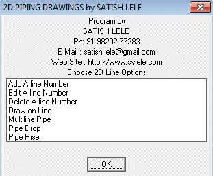 2D Pipe (pip) has 5 options:
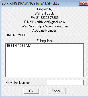 Add A line Number : When you click on this, a dialog box opens and shows the line numbers (names of layers) existing in the drawing, if any. You can add a new line number in the text box below. Program creates a new layer with that name.
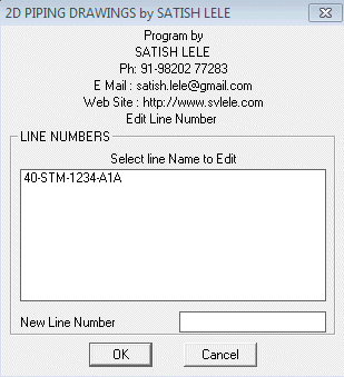 Edit A line Number : When you click on this, a dialog box opens and shows the line numbers (names of layers) existing in the drawing, if any. You can select the line number to be edited from the list and type a new line number in the text box below. Program renames that with a new name.
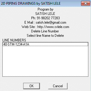 Delete A line Number : When you click on this, a dialog box opens and shows the line numbers (names of layers) existing in the drawing, if any. You can select the line number to be deleted from the list and line number and layer is deleted from the drawing, if line number and layer is not in use.
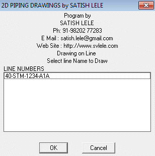 Draw on Line: When you click on this, a dialog box opens and shows the line numbers (names of layers) existing in the drawing, if any. You can select the line number from the list. Program makes the line number (layer) current, so that whatever you draw is put on that layer.
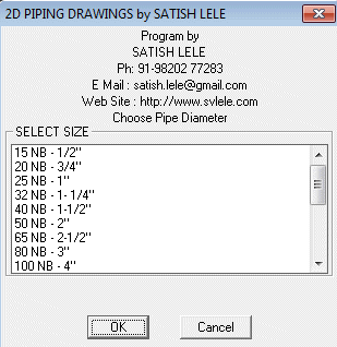 Multiline Pipe : This draws a line to its thickness. Select NB of Pipe and then pick pipe center line. Two lines are drawn along the center line, at a distance exactly equal to half the outside diameter of pipe. The linetype of the line changed to centerx2. Use this option after all fittings are drawn in that line.
 Pipe Drop : When pipe drops at the elbow, an arc is drawn showing direction of pipe going down. Select NB of Pipe in dialog box as above and then the point where drop will be there. Select a point at back of pipe. Arc will be put at the end.
 Pipe Rise :When pipe rises at the elbow, an arc is drawn showing direction of pipe coming up. Select NB of Pipe in dialog box as above and then the point where rise will be there. Select a point at back of pipe. Arc will be put at the end.
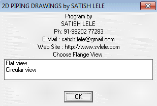 Flanges: You can draw Slip on, Weld Neck, Blind and BS10 Flanges. You can draw Flat or Circular view with this:
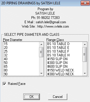
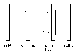 Flat View : Select the NB of Pipe and type and rating of flange. The raised face option is default. Select the insertion point of flange on pipeline and point at the back side of flange. A flange will be drawn and pipe will be cut.

 Circular View : Select the NB of Pipe and type and rating of flange. The raised face option is default. Select the insertion point of flange. A flange will be drawn. Flange will draw to appropriate number and size of bolt holes, at flange PCD.
Valve
Elevation
Valve
PlanGate Valve:
150# : From 15 mm NB to 600 mm NB.
300# : From 15 mm NB to 600 mm NB.
600# : From 15 mm NB to 600 mm NB.
800# : From 15 mm NB to 40 mm NB.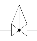
Valve
Elevation
Valve
PlanGlobe Valve:
150# : From 15 mm NB to 400 mm NB.
300# : From 15 mm NB to 300 mm NB.
600# : From 15 mm NB to 300 mm NB.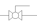
Valve
Elevation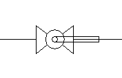
Valve
PlanBall Valve:
150# : From 15 mm NB to 150 mm NB.
300# : From 15 mm NB to 150 mm NB.
Valve
Elevation
Valve
PlanPlug Valve:
150# : From 15 mm NB to 600 mm NB.
300# : From 15 mm NB to 600 mm NB.
Butterfly
ValveWafer Butterfly Valve:
150# : From 50 mm NB to 600 mm NB.
Check
ValveNon-Slam Check Valve:
150# : From 50 mm NB to 1500 mm NB.
300# : From 50 mm NB to 1500 mm NB.
600# : From 50 mm NB to 1200 mm NB.
Check
ValveSwing Check Valve:
150# : From 15 mm NB to 350 mm NB.
300# : From 15 mm NB to 300 mm NB.
600# : From 15 mm NB to 300 mm NB.
800# : From 15 mm NB to 40 mm NB.
Check
ValveLift Check Valve:
150# : From 15 mm NB to 400 mm NB.
300# : From 15 mm NB to 300 mm NB.
600# : From 15 mm NB to 300 mm NB.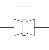
Valve
Elevation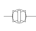
Valve
PlanPiston Valve:
150# : From 15 mm NB to 200 mm NB.
300# : From 15 mm NB to 200 mm NB. 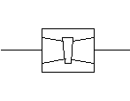
Jacketed
Plug
ValveFully Jacketed Plug Valve:
150# : From 25 mm NB to 250 mm NB.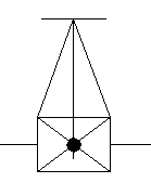
Jacketed
Globe
Valve
Elevation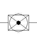
Jacketed
Globe
Valve
PlanFully Jacketed Globe Valve:
150# : From 25 mm NB to 300 mm NB.
300# : From 25 mm NB to 300 mm NB.
Gate
Valve
Elevation
Gate
Valve
PlanKnife Gate Valve:
150# : From 50 mm NB to 600 mm NB.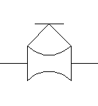
Valve
Elevation
Valve
PlanDiaphragm Valve:
150# : From 15 mm NB to 300 mm NB.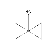
Valve
Elevation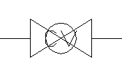
Valve
PlanControl Valve:
300# : From 15 mm NB to 200 mm NB.
600# : From 15 mm NB to 200 mm NB. 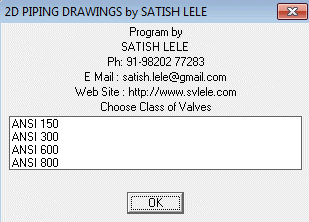

Window
Sight
Glass
View
Sight
Glass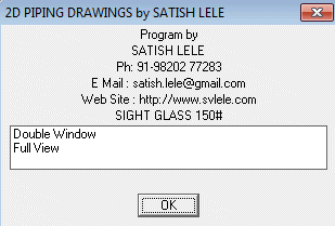

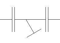
Steam TrapBall Float Steam Trap:
From 15 mm NB to 80 mm NB.
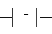
Steam TrapThermodynamic Steam Trap:
From 15 mm NB to 25 mm NB.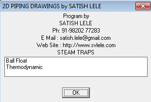
Flanged
Strainer
Elevation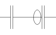
Flanged
Strainer
PlanY Type Flanged Strainer:
: From 50 mm NB to 600 mm NB.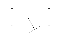
Socket Welded
Strainer
Elevation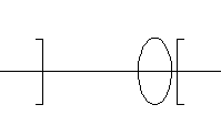
Socket Welded
Strainer
PlanY Type Socket Welded Strainer:
: From 8 mm NB to 100 mm NB.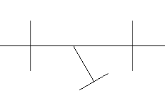
Screwed
Strainer
Elevation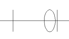
Screwed
Strainer
PlanY Type Screwed Strainer:
: From 8 mm NB to 100 mm NB.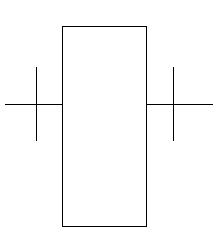
Strainer
Elevation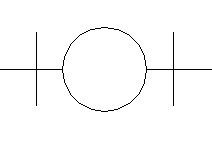
Strainer
PlanBasket Type Strainer:
: From 50 mm NB to 600 mm NB.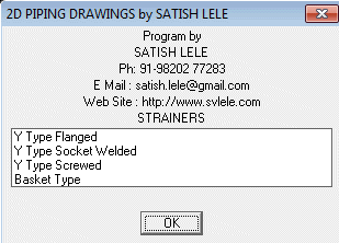

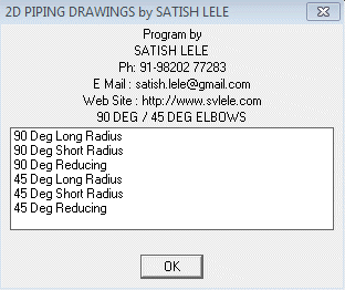
 90 Degree Elbow : You can draw an elbow of 15 mm NB to 600 mm NB by selecting a Point on First Pipeline, then a point on Second Pipeline and the Point of Intersection of two Lines. If two lines are not on same layer, program give error message and exits. Otherwise, Elbow is drawn at the intersection of two lines and pipe will be cut.
 45 Degree Elbow :
You can draw an elbow of 15 mm NB to 600 mm NB by selecting a Point on First Pipeline, then a point on Second Pipeline and the Point of Intersection of two Lines. If two lines are not on same layer, program give error message and exits. Otherwise, Elbow is drawn at the intersection of two lines and pipe will be cut.
 90 Degree Reducing Elbow :
You can draw a Reducing Elbow of 15 mm NB to 600 mm NB by selecting a Point on First Pipeline (Bigger dia), then a point on Second Pipeline (Smaller dia) and the Point of Intersection of two Lines. Elbow is drawn at the intersection of two lines and pipe will be cut.
 45 Degree Reducing Elbow :
You can draw a Reducing Elbow of 15 mm NB to 600 mm NB by selecting a Point on First Pipeline (Bigger dia), then a point on Second Pipeline (Smaller dia) and the Point of Intersection of two Lines. Elbow is drawn at the intersection of two lines and pipe will be cut.
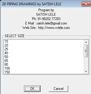

Equal Tee :
You can draw a Equal Tee of 25 mm NB to 600 mm NB by selecting a Point on Main Pipeline, then a point on Side Pipeline and the Point of Intersection of two Lines. Equal Tee is drawn at the intersection of two lines and pipe will be cut.
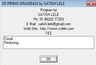
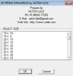
 Reducing Tee :
You can draw a Reducing Tee of 80 mm NB to 600 mm NB by selecting a Point on Main Pipeline, then a point on Side Pipeline and the Point of Intersection of two Lines. Reducing Tee is drawn at the intersection of two lines and pipe will be cut.

 Concentric Reducer
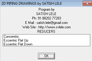
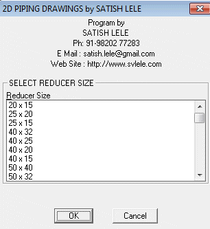
: You can draw a Concentric Reducer of 50 mm NB to 600 mm NB by selecting a Point on Main Pipeline where bigger end of reducer will be drawn, then a point on Pipeline towards lower side end. Reducer will be drawn and pipe will be cut.
 Eccentric Reducer Flat Up :
You can draw a Eccentric Reducer Flat Up of 50 mm NB to 600 mm NB by selecting a Point on Main Pipeline where bigger end of reducer will be drawn, then a point on Pipeline towards lower side end. Reducer will be drawn and pipe will be cut.
 Eccentric Reducer Flat Down :
You can draw a Eccentric Reducer Flat Down of 50 mm NB to 600 mm NB by selecting a Point on Main Pipeline where bigger end of reducer will be drawn, then a point on Pipeline towards lower side end. Reducer will be drawn and pipe will be cut.
 Swage :
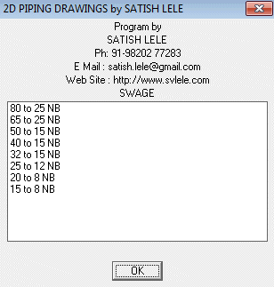
You can draw a Swage of 80 mm NB to 15 mm NB by selecting a Point on Main Pipeline where bigger end of Swage will be drawn, then a point on Pipeline towards lower side end. Swage will be drawn and pipe will be cut.
 Weldolet :
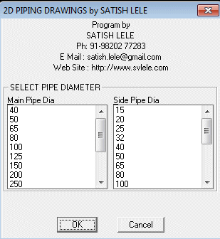
You can draw a Weldolet with this. Select NB of main pipe and side pipe. Select a Point on Main Pipeline, then a point on Side Pipeline and the Point of Intersection of two Lines. Weldolet is drawn at the intersection of two lines and pipe will be cut.
![]() Coupling :
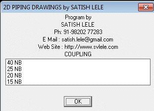
You can draw a Coupling by selecting a Point on Main Pipeline, then a point on Side Pipeline and the Point of Intersection of two Lines. Coupling is drawn at the intersection of two lines and pipe will be cut.
Coupling :
You can draw a Coupling by selecting a Point on Main Pipeline, then a point on Side Pipeline and the Point of Intersection of two Lines. Coupling is drawn at the intersection of two lines and pipe will be cut.
