 |
Satish Lele leleequip@gmail.com |
Heat exchangers are used to exchange heat between two fluids. The two fluids are separated by metal wall, through which heat transfer takes place. Double Pipe and Tubular exchangers are widely used.
- Exchangers recover heat between two process streams.
- Heaters are used primarily to heat, mainly by steam.
- Coolers are used to cool process fluids, mainly by water.
- Condensers are coolers which remove latent heat.
- Reboilers are heaters in process of distillation.
- Evaporators are used to concentrate solutions.
- Vapourizer removes any liquid other than water.
Double Pipe: In this there is a smaller pipe inside a larger pipe and two different fluids pass through these two pipes. There are a number of such pairs of tubes joined together by U bends. These are used if heat transfer area required is small. These are normally made of pipe sizes as follows:
Outer Pipe
NB InchInner Pipe
NB InchOuter Pipe
mm NBInner Pipe
mm NB2 1 1/4 50 32 2 1/2 1 1/4 65 32 3 2 80 50 4 3 100 80 Tubular: This is very widely used where larger surface area is required. Parallel tubes are fixed between two Tube Sheets. Tubes are enclosed by a shell. Fouling fluid flows in tubes and less fouling in shell. Channels are provided at two ends, for entry and exit of fluid into shell or tubes. Nozzles are attached to the shell and channel of exchanger. Channels have flanged connection with tube sheet. Gasket is provided for sealing.
Tubes are made of steel, copper, brass, cupro-nickel, bronze, aluminum or stainless steel. Tubes are of different thicknesses, defined by Birmingham Wire Gauge (BWG). 19mm (3/4") and 25mm (1") OD tubes are generally used.

If it is single pass exchanger you can select either Fixed head or Floating Shell.
If the number of passes is more than one, you can select either Fixed head, Floating head or Floating Shell.
In case of fixed head and floating shell, Diameter / PCD of both tube sheets will be same.
In case of floating head Diameter / PCD of Fixed Head tube sheet will be same as that Floating Head. However the Diameter / PCD of cover of floating head will be bigger.
In U Tube there is only one tube sheet, and it can have only two passes.
- Types of Heat Exchangers

Fixed Head Heat Exchanger: This is widely used, if the material of construction of shell and tubes is same. (Same amount of expansion of shell and tube). An expansion bellow is provided on shell in case there is uneven expansion. These are used if there is lower temperature difference between fluids in shell and tubes. Tubes can be cleaned from inside, but can not be cleaned from outside. Provides maximum heat transfer area for a given shell and tube diameter. Provides for single and multiple tube passes to assure proper velocity. Less costly than removable bundle designs. Shell side / out side of the tubes are inaccessible for mechanical cleaning. No provision to allow for differential thermal expansion developed between the tube and the shell side. This can be taken care by providing expansion joint on the shell side.

Floating Shell Heat Exchanger: Floating Shell Heat Exchanger is used if pressure on shell side is very small. (As in case of condenser). The shell is made up of two parts. These two are connected by stuffing box fixed to longer part. The smaller part of shell floats in stuffing box along gland packing.
Floating Head Heat Exchanger: Floating Head Heat Exchanger is used if the material of construction of shell and tubes is not same (Steel shell and copper tubes, where there is uneven expansion of shell and tubes). Floating Head Heat Exchanger are widely used in Petroleum Refineries, where sea water is as cooling medium in tubes. One head is fixed and floating head floats inside a bigger channel. Generally the floating head has no channel. Tube bundle can be removed from shell, and tubes can be cleaned from inside as well as outside. Floating tube sheet allows for differential thermal expansion between the shell and the tube bundle. Both the tube bundle and the shell side can be inspected and cleaned mechanically. To provide the floating-head cover, it is necessary to bolt floating head cover to the tube sheet. The bolt circle requires the use of space where it would be possible to place a large number of tubes. Tubes cannot expand independently so that huge thermal shock applications should be avoided. Packing materials puts limits on design pressure and temperature.
U Tube Heat Exchanger: A tube with U bend at center is attached to same tube sheet. Here the material of shell and tube can be different as uneven expansion is taken care by the cap on the other side. Replacement and cleaning of tubes is difficult. As there is only one tube sheet, U Tube Heat Exchanger is cheaper. Widely used as heater.
Smallest diameter of U bend is 3 times the OD of tube. Generally tubes in center line are omitted. U-tube design allows for differential thermal expansion between the shell and the tube bundle as well as for individual tubes. Both the tube bundle and the shell side can be inspected and cleaned mechanically. Less costly than floating head or floating shell designs. Because of U-bend some tubes are omitted at the center of the tube bundle. Because of U-bend, tubes can be cleaned only by chemical methods. Due to U-tube nesting, individual tube is difficult to replace. No single tube pass or true countercurrent flow is possible. Tube wall thickness at the U-bend is thinner than at straight portion of the tubes. Draining of tube circuit is difficult when positioned in vertical position with the head side upward.
Typical parts and connections for Floating Head are Floating Tube sheet, Tubes, Floating head cover, Floating head flange, Floating head gland, Floating head backing ring, Floating head support, Stationary tube sheet, Channel or stationary head, Channel cover, Channel nozzles, Tie rods and spacers, Transverse (or cross) baffles or support plates, Longitudinal baffles, Impingement baffles, Pass partition, Vent and Drain connections, Instrument connections, Support saddles, Lifting lugs etc.
The optimum thermal design of a shell and tube heat exchanger involves the consideration of many interacting design parameters which are as follows:
- Process
- Process fluid assignments to shell side or tube side.
- Selection of stream temperature specifications.
- Setting shell side and tube side pressure drop design limits.
- Setting shell side and tube side velocity limits.
- Selection of heat transfer models and fouling coefficients for shell side and tube side.
- Mechanical
- Selection of heat exchanger TEMA layout and number of passes.
- Specification of tube parameters - size, layout, pitch and material.
- Setting upper and lower design limits on tube length.
- Specification of shell side parameters – materials, baffle cut, baffle spacing and clearances.
- Setting upper and lower design limits on shell diameter, baffle cut and baffle spacing.
Q = U x A x Lmtd = w x Cp(t) x (t2 - t1) = W x Cp(s) x (T2 - T1)
Where Q is heat transferred per unit time (kJ/h, Btu/h)
U is overall heat transfer coefficient (kJ/h-m2 oC, Btu/h-ft2-oF)
A is heat-transfer area (m2, ft2)
Lmtd is log mean temperature difference (oC, oF)
Cp(t) is liquid specific heat tube side, Cp(s) is liquid specific heat shell side (kJ/kg-oC, Btu/lb-oF)
w is tube side flow, W is shell side flow (kg/h, lb/h)
T1 inlet shell side fluid temperature, (oC, oF)
T2 outlet shell side fluid temperature, (oC, oF)
t1 inlet tube side temperature, (oC, oF)
t2 outlet tube-side temperature, (oC, oF)
Lmtd = {(T1 - t2) - (T2 -t1)} / ln {(T1 - t2) / (T2 -t1)}
In design, a correction factor is applied to the LMTD to allow for the departure from true countercurrent flow to determine the true temperature difference. The correction factor is a function of the fluid temperatures and the number of tube and shell passes and is correlated as a function of two dimensionless temperature ratios, R and S. FT normally should be greater than 0.75 for the steady operation of the exchangers. Otherwise it is required to increase the number of passes to obtain higher FT values.
- Design Parameters of Heat Exchanger
Pressure: Design pressure for calculating thickness of shell and tube is generally 5% to 10% higher than maximum operating pressure.
Temperature: Design temperature is 10 deg C higher than maximum operating temperature.
- Parameters of Parts of Heat Exchanger
Shell: Internal diameter of shell depends on outer tube limit. Shell can be made from standard pipe or by rolling a plate.
Tubes: These can be plain or finned.
Tube OD: Most important parameter for Heat Exchange is Outer Diameter of Tube. Higher the tube diameter, greater is the heat transfer area. OD of tube is generally 19 mm, 25 mm, 32 mm (3/4", 1", 1 1/4" ) or higher.
Tube Pitch is the distance between center lines of two tubes. Normally distance between center lines is equal to next tube size. For metric units, distance between center lines is generally 25 mm (for 19 mm OD tube), 32 mm (for 25 mm OD tube), 40 mm (for 32 mm OD tube). For imperial units, distance between center lines is generally 1" (for 3/4" OD tube), 1 1/4" (for 1" OD tube), 1 1/2" (for 1 1/4" OD tube).
Tube length is end to end length of tube. Tube length includes distance between two tube sheets, length of tubes inside tube sheet and extension outside tube sheet. Tube extension is projection length of tube outside the tube sheet (in head portion). Number of tubes depends on Heat Transfer Area required and OD of tubes.

Tube Sheet: Tube Sheet is a flat, circular plate. If the tube sheet material is not expensive, like Carbon Steel, you can select Tube sheet with flange. If the tube sheet material is expensive, like Stainless Steel, Hastelloy, Monel, you can select Tube sheet without flange. Flange is made of Carbon Steel. Based on Number of tubes, Outer Tube Limit can be calculated, OD and PCD of tube sheet as well as number of bolt holes and diameter of bolt holes will depend on outer tube limit. Gap between Outer Tube Limit and shell ID, Shell thickness can be set.
Gasket width is for circular part as well as for dividing partitions for fixed tube sheet and floating tube sheet. Gasket thickness is one that is as per manufacturers sizes.

Tube Configurations: Once these tube parameters are fixed, you select the tube configuration. Tubes are usually not laid symmetrically in tube sheet. Extra entry space is provived in shell by omitting tubes directly under inlet nozzle. Outer tube limit shows the circle encompassing all the tubes. In multi-pass exchangers, number of tubes is not same in every pass. (Unbalance should not be more than 5%). When larger nozzles are used, inlet nozzle is flared to have larger entry area.
There are 4 options. You can select either Square pitch, Triangular pitch, Rotated Square pitch or Rotated Triangular pitch. Square and Triangular pitch are normally used as this Tube Configuration facilitates cleaning of the tube externally.Number of Passes on Tube Side: Fluid velocity on tube side, is division of flow rate on tube side and Cross sectional area of all tubes. This should be 1 to 3 meters (or 3 to 10 feet) per second. If velocity is less than these values, velocity is increased by selecting more number of passes. You can select either 1, 2, 4, 6 8, 10 or 12 passes on tube side.
- Arrangement of Tubes for different tube configurations and passes
Channel and Channel Cover: These are fabricated from plates. The thickness depends on pressure on tube side. The length of channel is higher if there is a partition plate. There are 3 types Heads. Torispherical, Flanged or Flat. Flange connected to channel can be standard Slip-on or Weld Neck Pipe flanges.
- Nozzles: Following nozzles are generally provided on a Heat Exchanger
- Inlet and Outlet on Shell side
- Inlet and Outlet on Tube side
- Instrument connections
- Drains on Inlet and Outlet on Shell side nozzles
- Drains on Inlet and Outlet on Shell side nozzles
Baffles: Baffles are used to produce turbulence outside tubes. Baffles make shell side liquid to flow at right angle to tubes. Distance between two baffles is generally equal to inside diameter of shell. There can be 6 types of baffles. Baffles are held in position by tie rods. First four baffles are commonly used. These baffles are called 25% cut baffles. Top/Bottom cut baffles are used for liquids, while side cut baffles are used for liquid with gases or for vertical exchanger.


Tie Rods: Generally there are 4 or 6 Tie Rods, Diameter of Tie Rods depends on strength required. Length of Tie Rods will be based on length of tube. Spacers are put on tie rods to keep proper gap in baffles.
Davit: A davit is provided for channel flange.
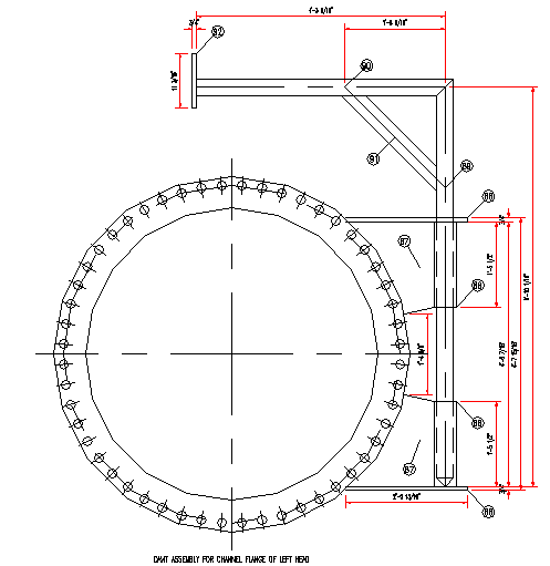
Material of Construction: Heat Exchanger can have combinations of Material of Construction.

Saddle Support is provided for Horizontal exchangers and lugs for Vertical exchangers.

- There are some special types of heat exchangers
- Pipe Coils
- Spiral Heat Exchangers
- Plate Heat Exchangers
- Finned Tube Heat Exchangers
- Graphite Heat Exchangers

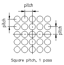
This Arrangement of Tubes has tubes in central line in both direction. Each tube center is one pitch distance left or right. Next tube center is one pitch distance up or down.
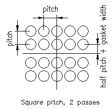
This Arrangement of Tubes has no tubes in horizontal central line, but tubes exists in vertical direction along central line. First vertical line is half pitch distance above or below centerline. Each tube in horizontal center is one pitch distance left or right. Next tube center is one pitch distance up or down.
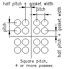
This Arrangement of Tubes has a no central line in horizontal and vertical direction. First line in horizontal and vertical direction is half pitch distance above or below / left or right of centerline. Next tube center is one pitch distance up or down.
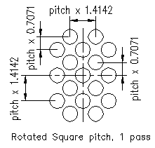
This Arrangement of Tubes has a central line in both direction. Each tube in centerline is one pitch distance x phfact left or right. First vertical centerline is one pitch x pvfact distance up or down. First horizontal centerline is half pitch distance x phfact left or right of centerline. Second centerline in vertical direction is one pitch distance x pvfact above or below.
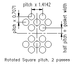
This Arrangement of Tubes has a no central line in horizontal direction, but exists in vertical direction. First line is half pitch distance + gasket width above or below centerline. Each tube center is one pitch x phfact distance left or right. Next tube center is one pitch distance x pvfact up or down.
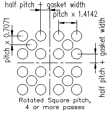
This Arrangement of Tubes has a no central line in horizontal and vertical direction. First line in horizontal direction is half pitch distance + gasket width left or right of centerline. First line in vertical direction is half pitch distance + gasket width above or below centerline. Each tube center in horizontal direction is one pitch distance x phfact left or right. Each tube centerline in vertical direction is one pitch distance x pvfact above or below.
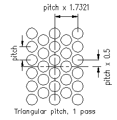
This Arrangement of Tubes has tubes in central line in both direction. First horizontal line is half pitch above center line. Each tube center is one pitch distance in vertical direction and pitch x 1.7321 in horizontal direction.
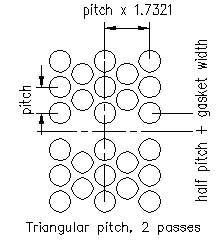
This Arrangement of Tubes has no tubes in horizontal central line but has a line of tube in vertical direction. First horizontal line is half pitch above / below center line. Each tube center is one pitch + gasket width distance in vertical direction and pitch x 1.7321 in horizontal direction.
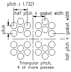
This Arrangement of Tubes has no tubes in horizontal and vertical central line. First horizontal and vertical line is half pitch up/ down /above / below center line. Each tube center is one pitch + gasket width distance in vertical direction and pitch x 1.7321 in horizontal direction.
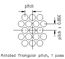
This Arrangement of Tubes has tubes in central line in both direction. First horizontal line is pitch x 0.866 above center line. Each tube center is one pitch distance in horizontal direction and pitch x 0.866 in vertical direction.
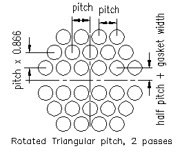
This Arrangement of Tubes has tubes in central line in vertical direction. First horizontal line is half pitch + gasket width above center line. Each tube center is one pitch distance in horizontal direction and pitch x 0.866 in vertical direction.
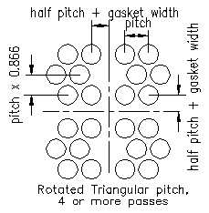
This Arrangement of Tubes has no tubes in central lines in both directions. First horizontal and vertical line is half pitch + gasket width above center line. Each tube center is one pitch distance in horizontal direction and pitch x 0.866 in vertical direction.
 Piping Training
