 |
Satish Lele leleequip@gmail.com |
|
 to Request for Demo Design Program for Tubular Heat Exchanger. to Request for Demo Design Program for Tubular Heat Exchanger. |
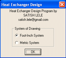
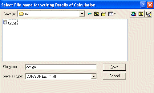
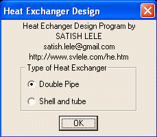
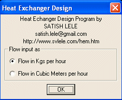
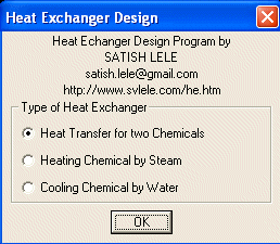
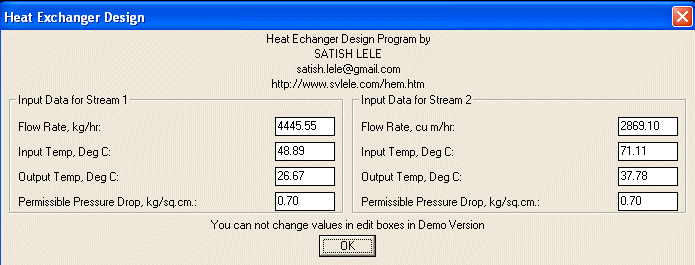
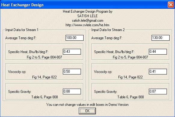
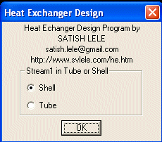
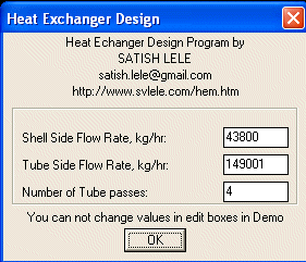
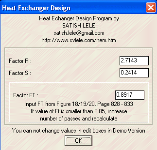
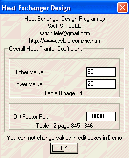
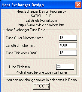
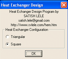
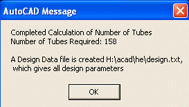
The Design Program for Tubular Heat Exchanger asks for parameters in the following dialog boxes, and based on these values, Design Program for Tubular Heat Exchanger designs.
Design Program for Tubular Heat Exchanger first picks up flow rates, and then inlet and outlet temperatures for two streams. Out of these six values, if one is not known, Design Program for Tubular Heat Exchanger calculates values, based on other five. Design Program for Tubular Heat Exchanger also asks for permissible pressure drop on two streams. Design Program for Tubular Heat Exchanger then calculates average temperatures of two streams. Based on these average temperatures, Design Program for Tubular Heat Exchanger asks for specific heat, viscocity and specific gravity of two streams.
Stream with lower flow rate and higher temperature difference is placed Shell side. The number of passes on tube side is ratio of flow rate on tube side to flow rate on shell side, which is rounded to even number. Report Generated by Design Program for Tubular Heat Exchanger ============================================================== *Process Design Units of Calculation : Imperial Input Values in Metric system ============================================================== Type : Shell and Tube Heat Exchanger ============================================================== Duty : Inter Changer for two Chemicals ============================================================== *Input Parameters Shell side flow rate : 19510.00 kg/h Shell side inlet Temp : 198.89 Deg C Shell side outlet Temp : 93.33 Deg C Shell side Allowable Pressure Drop : 0.35 Kg/sq.cm. Shell side liquid Specific Heat : 0.6128 Btu/lb-Deg F Shell side liquid Viscosity : 0.40 cP Shell side Specific Gravity : 0.7300 Tube side flow rate : 67605.00 kg/h Tube side inlet Temp : 76.67 Deg C Tube side outlet Temp : 37.78 Deg C Tube side Allowable Pressure Drop : 0.70 Kg/sq.cm. Tube side liquid Specific Heat : 0.4890 Btu/lb-Deg F Tube side liquid Viscosity : 3.60 cP Tube side Specific Gravity : 0.8300 ============================================================== Stream 1 on Shell side Number of Tube Side Passes : 4 Factor R : 2.7143 Factor S : 0.2414 Factor Ft : 0.8917 Corrected LMTD : 135.71 Dirt Factor Rd : 0.0030 Heat Transfer Load : 5100320.06 Btu/hr ============================================================== *Tube Data Tube Outer Diameter : 25 mm Length of Tube : 4800 mm Tube Thickness BWG : 13 Tube Pitch : 32 mm Tube Configration : Square ============================================================== *All Calculations done in Imperial Units Tube Side Flow Area : 0.1404 sq. ft. Tube Side Mass Velocity : 1061465.81 ft/h Tube Side Reynold's Number : 8224 Tube Side jH value : 30.2000 Tube Side mean Temp : 129.40 Deg F Tube side c Value : 0.4900 Tube side k Value : 0.0770 Tube side Heat Transfer Coefficient h : 106 Btu/h-sq. ft. Deg F Tube side Heat Transfer Coefficient h (corrected for viscocity) : 120 Btu/h-sq. ft. Deg F Shell Side Flow Area : 0.1442 sq. ft. Shell Side Mass Velocity : 298095.66 ft/h Shell Side Reynold's Number : 25662 Shell Side jH value : 92.0000 Shell Side mean Temp : 279.80 Deg F Factor Fc : 0.42 Shell side c Value : 0.59 Shell side k Value : 0.08 Shell side Heat Transfer Coefficient h : 165.06 Btu/h-sq. ft. Deg F Shell side Heat Transfer Coefficient h (corrected for viscocity) : 157.47 Btu/h-sq. ft. Deg F ============================================================== *Pressure Drop in Imperial Units Shell side Pressure Drop Shell Side Reynold's Number : 25662 Shell side passes : 40 Gap in Baffles : 4 7/8" Shell side Friction Factor : 0.0018 Shell side Mass Velocity : 298095.66 ft/h Shell ID : 1'-9 1/4" Shell Liquid specific gravity : 0.7300 Equivalent Dia of Tube : 1 Shell side Pressure Drop : 0.2608 kg/sq cm -------------------------------------------------------------- Tube side Pressure Drop Tube Side Reynold's Number : 8224 Tube side passes : 4 Tube side Friction Factor : 0.0003 Tube Liquid specific gravity : 0.8300 Tube Side Mass Velocity : 1061465.81 ft/h Length of Tube : 4800 mm Inside Dia of Tube : 1 Tube side Friction Loss : 0.4523 kg/sq cm Velocity Head : 0.1700 psi Tube side Velocity Loss : 0.2302 kg/sq cm Tube side Pressure Drop : 0.6827 kg/sq cm ============================================================== Summary: Number of Tubes : 158 Shell side passes : 40 Number of Baffles : 39 Recommended Shell NB : 550 mm Gap in Baffles : 124 mm ============================================================== |
 |
Heat Echanger Agitator Design Program Agitator Design Program |
 |
 DoublePipe
 Exchanger