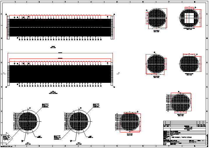
A GA Drawing of Tube Bundle and baffles for double pass Tubular Exchanger with floating head. Drawing Program shows tags to each component.
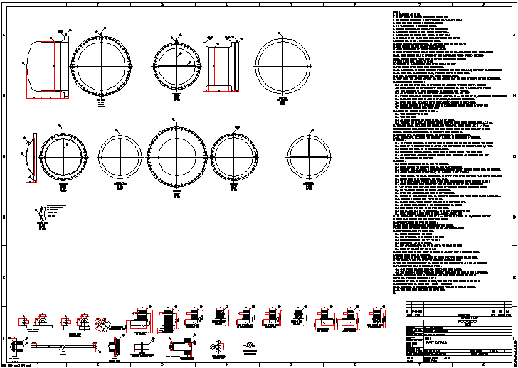
A Drawing of Heads and Gaskets for double pass floating head. Drawing Program shows details at bottom and Drawing Program writes the notes on right.
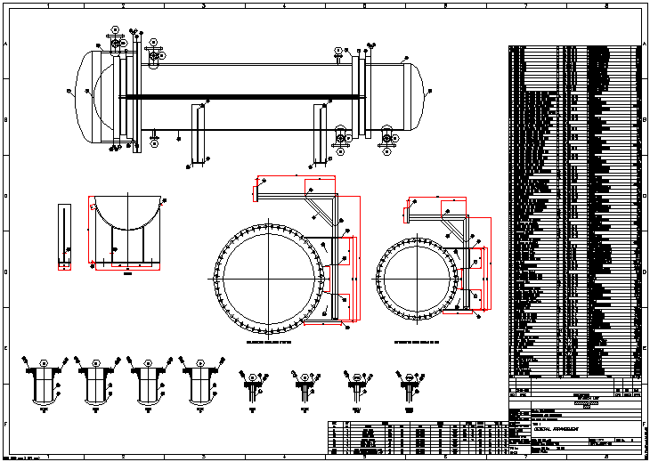
Complete GA Drawing of Exchanger, details of saddle, Nozzles and Nozzle table. Drawing Program also writes Bill of Material for each component with reference to tag number.
To run the program, unzip he.zip and copy files in one folder on hard disk (and not on desk top), say he. While running inexpensive CAD program like BricksCAD Lite, ProgeCAD, IntelliCAD, Draftsight, CADLogic, click on tools ->Options (or Preferences) -> Files -> + of Support File Search Path -> Add -> Browse -> Select the folder (he), and click on apply. The he.zip file contains he.lsp, he.dcl and he.slb, other lsp files, A1.dwg (Border drawing) and trial.dwg (dummy drawing).
To run the program always open trial.dwg and load he.lsp by appload or by typing (load "he.lsp") at command prompt and press <enter> or use APPLOAD command. (If you get message "File not found", please set up folder path settings again.) Type agit and press <enter> and program will start. The produced drawing can be saved in any folder you select and by the name you decide.
The program asks for parameters in the following dialog boxes, and based on these values it draws.
Dialog Box 1 : You can select the Foot-Inch units or Metric Units for the drawing. The system variables will be set automatically to draw in either Foot-Inch or Metric Units. All inputs will also be in selected unit system.
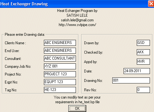
Dialog Box 2 : Enter designer data which will reflect in the title block of drawing. Program will automatically selects date.
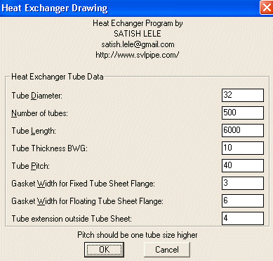
Dialog Box 3 : You can select Outer Diameter of Tube. OD is generally 19 mm, 25 mm, 32 mm or higher. Correspondingly you select Tube Pitch. Tube Pitch is generally 25 mm (for 19 mm tube), 32 mm (for 25 mm tube), 40 mm (for 32 mm tube). Tube Pitch is the distance between center lines of two tubes. Tube length is end to end length of tube. Gasket width is for circular part as well as for dividing line for fixed tube sheet and floating tube sheet. Tube extension is projection length of tube outside the tube sheet (in head portion). You can select any number of tubes from 1 to 1,000. This will be extended to 2000 tubes. You can fix gasket thickness.
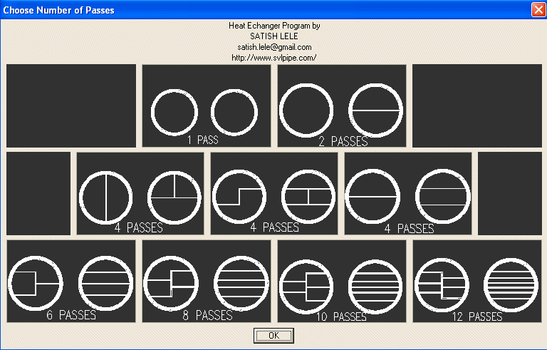
Dialog Box 4 : You can select either 1, 2, 4, 6 8, 10 or 12 passes on tube side.
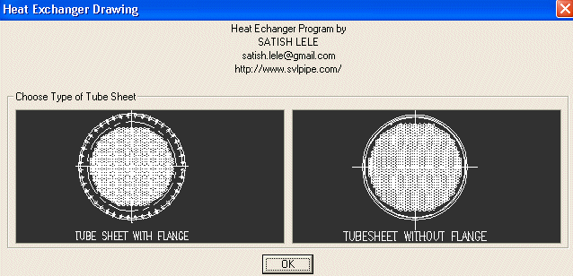
Dialog Box 5 : You can select Tube sheet with flange or without flange.
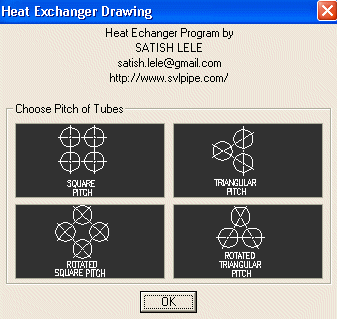
Dialog Box 6 : Once these tube parameters are fixed, you select the tube configuration. There are 4 options. You can select either Square pitch, Triangular pitch, Rotated Square pitch or Rotated Triangular pitch. Square and Triangular pitch are normally used as these configurations facilitate cleaning of the tube externally. Configuration for different passes is shown below.
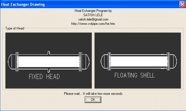
Dialog Box 7 : If exchanger is 1 pass, you can select either Fixed head or Floating Shell. In case of fixed head and floating shell, Diameter / PCD of both tube sheets will be same.
OR
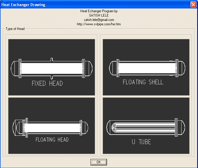
Dialog Box 7 : If exchanger has multiple passes, you can select either Fixed head, Floating head, Floating Shell or U Tube. In case of fixed head and floating shell, Diameter / PCD of both tube sheets will be same. In case of floating head Diameter / PCD of Right (Fixed Head) tube sheet will be smaller than that one on Left (Floating Head). In U Tube there is only one tube sheet.
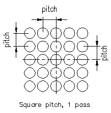
Tubular Heat Exchanger has tubes in central line in both direction. Each tube center is one pitch distance left or right. Next tube center is one pitch distance up or down.
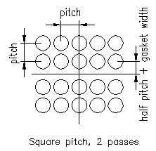
Tubular Heat Exchanger has no tubes in horizontal central line, but tubes exists in vertical direction along central line. First vertical line is half pitch distance above or below centerline. Each tube in horizontal center is one pitch distance left or right. Next tube center is one pitch distance up or down.
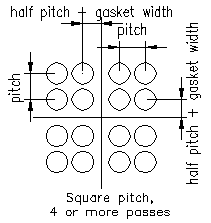
Tubular Heat Exchanger has a no central line in horizontal and vertical direction. First line in horizontal and vertical direction is half pitch distance above or below / left or right of centerline. Next tube center is one pitch distance up or down.
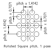
Tubular Heat Exchanger has a central line in both direction. Each tube in centerline is one pitch distance x phfact left or right. First vertical centerline is one pitch x pvfact distance up or down. First horizontal centerline is half pitch distance x phfact left or right of centerline. Second centerline in vertical direction is one pitch distance x pvfact above or below.
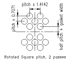
Tubular Heat Exchanger has a no central line in horizontal direction, but exists in vertical direction. First line is half pitch distance + gasket width above or below centerline. Each tube center is one pitch x phfact distance left or right. Next tube center is one pitch distance x pvfact up or down.
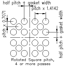
Tubular Heat Exchanger has a no central line in horizontal and vertical direction. First line in horizontal direction is half pitch distance + gasket width left or right of centerline. First line in vertical direction is half pitch distance + gasket width above or below centerline. Each tube center in horizontal direction is one pitch distance x phfact left or right. Each tube centerline in vertical direction is one pitch distance x pvfact above or below.
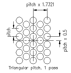
Tubular Heat Exchanger has tubes in central line in both direction. First horizontal line is half pitch above center line. Each tube center is one pitch distance in vertical direction and pitch x 1.7321 in horizontal direction.
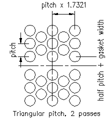
Tubular Heat Exchanger has no tubes in horizontal central line but has a line of tube in vertical direction. First horizontal line is half pitch above / below center line. Each tube center is one pitch + gasket width distance in vertical direction and pitch x 1.7321 in horizontal direction.
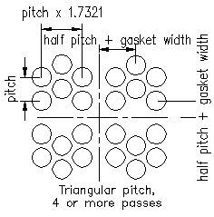
Tubular Heat Exchanger has no tubes in horizontal and vertical central line. First horizontal and vertical line is half pitch up/ down /above / below center line. Each tube center is one pitch + gasket width distance in vertical direction and pitch x 1.7321 in horizontal direction.
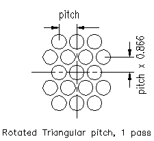
Tubular Heat Exchanger has tubes in central line in both direction. First horizontal line is pitch x 0.866 above center line. Each tube center is one pitch distance in horizontal direction and pitch x 0.866 in vertical direction.
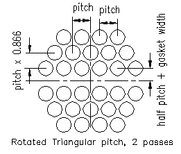
Tubular Heat Exchanger has tubes in central line in vertical direction. First horizontal line is half pitch + gasket width above center line. Each tube center is one pitch distance in horizontal direction and pitch x 0.866 in vertical direction.
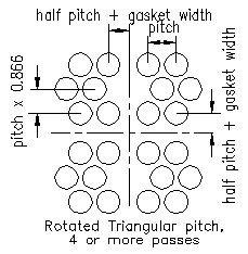
Tubular Heat Exchanger has no tubes in central lines in both directions. First horizontal and vertical line is half pitch + gasket width above center line. Each tube center is one pitch distance in horizontal direction and pitch x 0.866 in vertical direction.
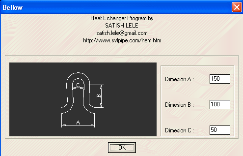
In case of Fixed Head, you can select sizes of expansion Bellow.
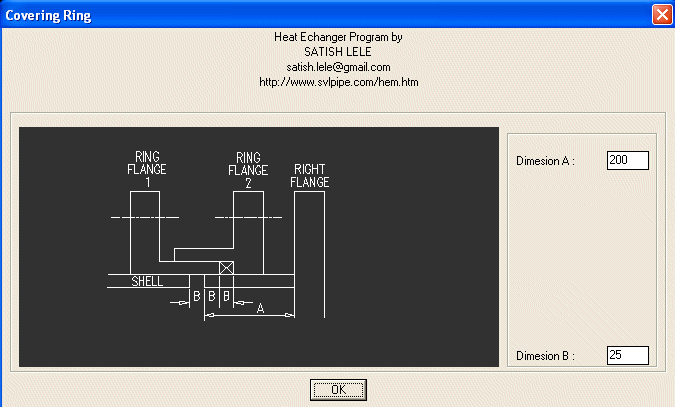
In case of Floating Shell, you can select sizes of Floating Ring.
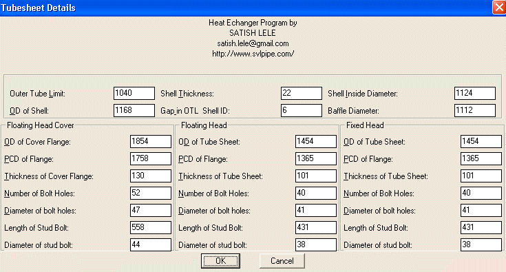
Dialog Box 8 : In case of Floating Head, based on Number of tubes, program will indicate Outer Tube Limit, OD and PCD of tube sheet as well as number of bolt holes and diameter of bolt holes. Drawing Program will indicate shell thickness and Gap between Outer Tube Limit and shell ID in Left Column and that for Fixed head in Right Column. In case of Fixed Head, only values in Left column will be shown.
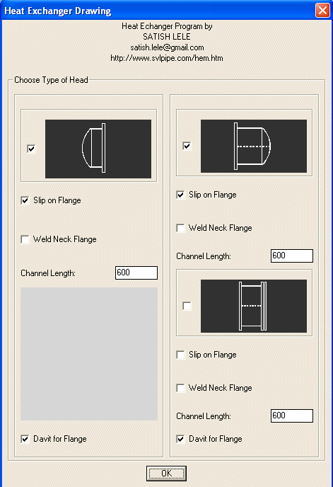
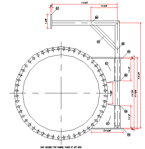
Dialog Box 9 : You can select Heads, Type of flange and Length of channel. Also you can specify whether a davit is required for channel flange.
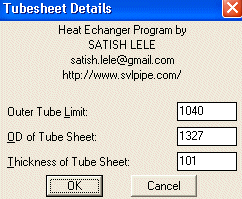
Dialog Box 10 : This indicates values for tube sheet.
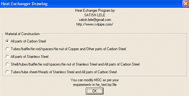
Dialog Box 11 : You can select combinations of Material of Construction.
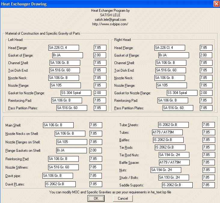
Dialog Box 12 : You can select Details of Material of Construction.
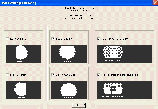
Dialog Box 13 : In this you can select 6 types of baffles. Select Left Cut and Right Cut for Vertical Heat Exchangers. For Horizontal Heat Exchangers, select Top Cut and Bottom Cut. Other two are optional. Select by checking the check boxes.
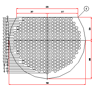
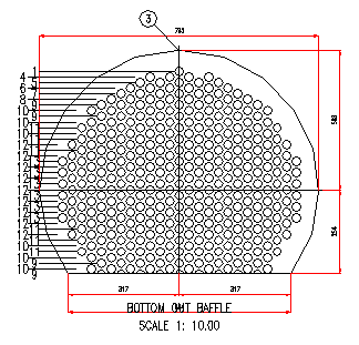
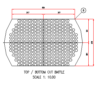
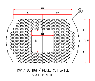
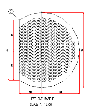
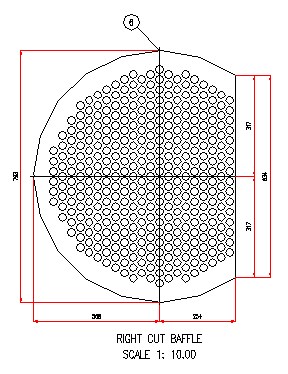
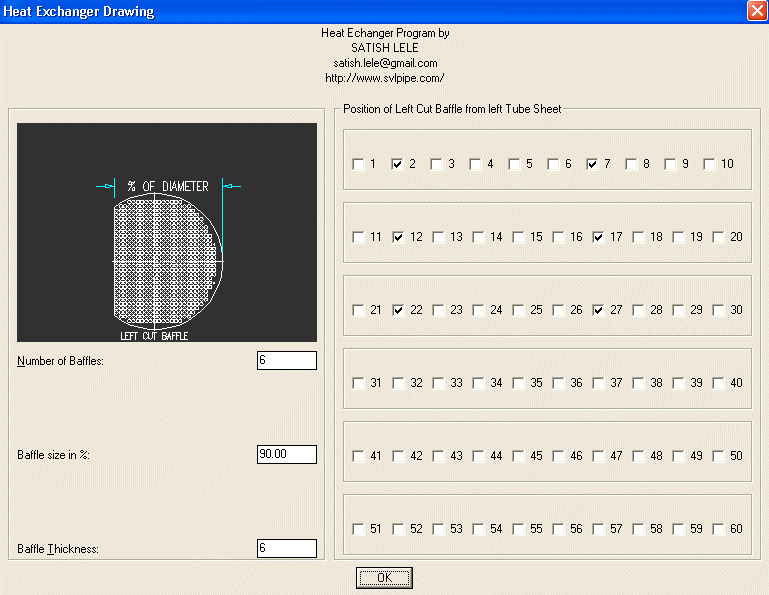
Dialog Box 14 : Dialog boxes of these will be displayed if you select these in earlier box. You have to indicate the location of particular baffles.
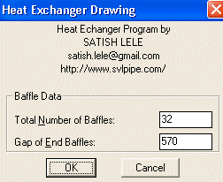
Dialog Box 15 : In this box you can select Total Number of Baffles (these include two baffles at end, and cut baffles). End baffles are generally placed away from tube sheet for nozzle, hence you have to indicate Gap of End Baffles. Gap in Other Baffles is generally uniform. You can choose Thickness of Baffle. For Top / Bottom cut Baffles, you can indicate baffle size as % of diameter. For Top / Bottom / Center cut Baffle, you can indicate vertical and horizontal % of diameter, as vacant area.
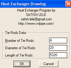
Dialog Box 16 : In this box you can select Number of Tie Rods, Diameter of Tie Rods, Length of Tie Rods will be indicated based on length of tube.
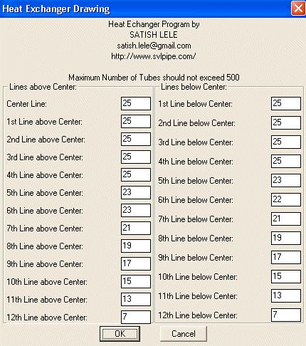
Dialog Box 17 : The Dialog Box shows number of tubes in each row above and below center line of tube sheet. You can change these, but total tubes should not exceed number of tubes selected earlier. (The box shown is for 500 tubes.)
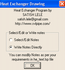
Dialog Box 18 : This offers you two options. Either you can write Notes that are generally written or you can select/edit each note.
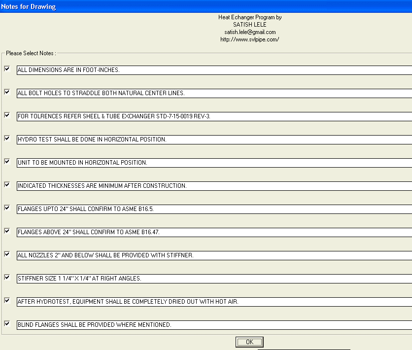
Dialog Box 19 : If you select edit option, you can see and edit each note. If you uncheck any box, that note will be deleted. You will get 10 number of boxes with more notes.
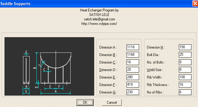
Dialog Box 20 : You can select dimensions for Saddle Support.
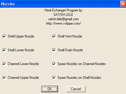
Dialog Box 21 : You can select Nozzles attached to the exchanger.
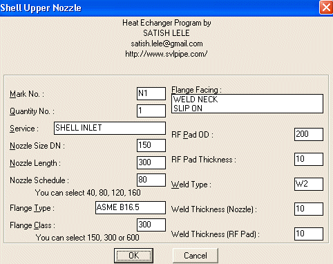
Dialog Box 22 : You can select Parameters for each Nozzle attached to the exchanger. Nozzle will be drawn as detail and tags will be given to all components. Its components will be added to Bill of Material.
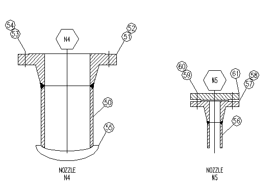

Dialog Box 23 : Nozzles drawn as detail with tags and Nozzle Table.

Dialog Box 24 : You will be instructed to insert each Nozzle attached to the exchanger. Select nearest or mid point to insert nozzle. Select angle of rotation. Irrespective of rotation, nozzle number will be displayed horizontally.
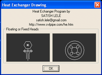
Dialog Box 25 : You will be instructed to select either side or circular Nozzle in case of smaller nozzles. Select nearest or mid point to insert nozzle.


 to Download Loading Instructions for Heat Exchanger Package.
 to Download Catalog for Heat Exchanger in metric units.
 to Download Information about Heat Exchanger.
 to Download Input Data Sheet.
 Agitator / Mixer Manual


