 |  |
Satish Lele lelepiping@gmail.com |
View this page as YouTube Video Presentation
Process Flow Drawing (PFD): A process flow diagram (PFD) is a diagram commonly used in chemical and process engineering to indicate the general flow of plant processes and equipment. The PFD displays the relationship between major equipment of a plant facility and does not show minor details such as piping details and designations.
A Process Flow Diagram (PFD) shows the relationships between the major components in the system. PFD also tabulate process design values for the components in different operating modes, typical minimum, normal and maximum. A PFD does not show minor components, piping systems, piping ratings and designations.
- Typically, process flow diagrams of a single unit process will include the following:
- Major equipment items.
- All equipment sizes with relevant MEB information as required.
- All equipment names and numbers
- Process piping.
- All major process lines.
- All major utility lines involving material flow.
- All stream numbers, temperatures, pressures, flows.
- Control valves and other major valves.
- Connections with other systems.
- Major bypass and recirculation streams.
- Operational data (temperature, pressure, mass flow rate, density, etc.).
- Process stream names.
- Conveys the major processing steps represented by the equipment:
- Useful for conveying the heat and material balances.
- Useful for conveying major pieces of equipment.
- Useful for conveying processing conditions.
- Useful for conveying utilities.
- The goal is to present the most amount of information with the least amount of effort on the part of the reader.
- The flowsheet should generally flow from left to right.
- The flowsheet should not be cluttered - use multiple sheets.
- The flowsheet should be in landscape with the bound edge at top.
- The equipment should be drawn in approximately relative size, e.g. towers larger than drums, exchangers larger than pumps etc.
- The major towers and reactors are generally on one, or nearly one, level.
- The reader should be able to follow Piping and Instrumentation Diagrams with his or her eye.
- The streams should have the minimum of direction changes.
- The streams that enter across the battery limits should be on the left.
- The streams that leave across the battery limits should be on the right.
- The streams that move to the next sheet should leave on the right.
- The streams that recycle to earlier sheets should leave on the left.
- Process flow diagrams generally do not include:
- Pipe classes or piping line numbers.
- Process control instrumentation (sensors and final elements).
- Minor bypass lines.
- Isolation and shutoff valves.
- Maintenance vents and drains.
- Relief and safety valves.
- Flanges.
Process flow diagrams are high levels drawings usually of multiple process systems within a large industrial plant and may be called block flow diagrams or schematic flow diagrams.
Piping and Instrumentation Diagram (P&ID): The P&ID shows the interconnection of process equipment and the instrumentation used to control the process. In the process industry, a standard set of symbols is used to prepare P&ID drawings of processes. Piping and Instrumentation Diagram is a diagram in the process industry which shows the piping of the process flow together with the installed equipment and instrumentation.
- For processing facilities, a Piping and Instrumentation Diagrams is a pictorial representation of the following:
- Key piping and instrument details.
- Relationship between control instruments and process equipment.
- Control and shutdown schemes.
- Safety and regulatory requirements.
- Basic start up and operational information.
- Instrumentation and designations.
- Mechanical equipment with names and numbers.
- All valves and their identifications.
- Process piping, sizes and identification.
- Miscellanea -vents, drains, special fittings, sampling lines, reducers, increasers and swages.
- Permanent start-up and flush lines.
- Flow directions.
- Interconnections references.
- Control inputs and outputs, interlocks.
- Interfaces for class changes.
- Computer control system input.
- Identification of components and subsystems delivered by others.
- What information can you get?:
- For Equipment: Outline/Internals.
- For Piping: Line No./Size/Material/Insulation/Line Configuration/Piping Component Type.
- For Instrument: Tag No./Function/Control Method.
- P&ID is used for
- Detail Engineering of each disciplines Piping layout / Material Purchase Instrument Logic / DCS Plan, etc.
- Planning of Construction / Commissioning /Plant Operation / Maintenance
As a rule Piping and Instrumentation Diagrams do not have a drawing scale and present only the relationship or sequence between components. Just because two pieces of equipment are drawn next to each other does not indicate that in the plant the equipment is even in the same building, Piping and Instrumentation Diagram is just the next part or piece of the system. These drawings only present information on how a system functions, not the actual physical relationships. Because P&IDs provide the most concise format for how a system should function, they are used extensively in the operation, repair, and modification of the plant.
Piping and Instrumentation Diagrams play a significant role in the maintenance and modification of the process that Piping and Instrumentation Diagram describes. It is critical to demonstrate the physical sequence of equipment and systems, as well as how these systems connect. During the design stage, the diagram also provides the basis for the development of system control schemes, allowing for further safety and operational investigations, such as the hazard and operability study(HAZOP)
- Key Points:
- Place equipment and its components.
- Connect main piping.
- Complete control valve loop.
- Place other instrument and connect signals.
- Indicate safety devices including alarm.
- Place piping components (Valve / Fitting) as required.
- Check detail and add items required including vent / drain connection
Identify and draw Piping and Instrument Diagram (P&ID) symbols frequently used for valves instruments and equipment.
Identify and draw isometric symbols used for screwed and butt welded fittings for piping systems.
Identify and draw pipe General Arrangement (GA) symbols that are used for piping general arrangement drawings.
Sketch single line piping isometric for the piping assembly spools.
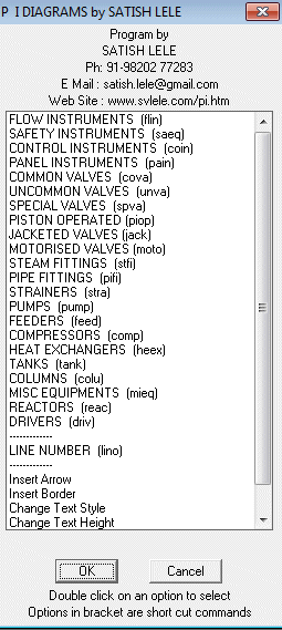
Most inexpensive CAD program like BricksCAD, ProgeCAD, IntelliCAD, Draftsight, CADLogic, ZWCAD or FreeCAD Packages are prepared in such a manner that these can be easily customized. 4 Programs of OpenPipe are such customized programs. The pi program is based on LISP and symbols or blocks are created as and when required and then inserted. Bill of Material is created by a VBA program, which creates a table in MS Excel. In case of valves, the pipe line is cut in that portion. Since blocks are created each time, there is a lot of saving of Disk space. Since the program is written in LISP, Piping and Instrumentation Diagram program can be even modified further. The different pipe lines are arranged on different layers. This is a program where options can be selected through Dialog Boxes. Special Dialogue Boxes are created to make the program more user friendly.
To try the program, send a request for trial package. The package is a zip file, pi_trial.zip. There is no setup.exe file as in other packages. Download and unzip pi_trial.zip and copy files in a folder. While running inexpensive CAD program like BricksCAD, ProgeCAD, IntelliCAD, Draftsight, CADLogic, ZWCAD or FreeCAD program, click on tools ->Options (or Preferences) -> Files -> + of Support File Search Path -> Add -> Browse -> Select the folder. The pi_trial.zip file contains pi*.lsp, pi.dcl and pi.slb, pi.dwg (Border drawing). At command prompt type (load "pi.lsp") and press enter. pi program will be loaded. Type pid and press enter. A dialog box will open showing all options of pi. Start selecting options from Dialog Box.
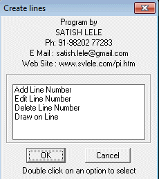
Dialog box to Select Create / Edit / Delete Lines : The lines are arranged on different layers, and the layer name is same as line number. The line number is generally in format : Size-Service-Line Number-Spec.
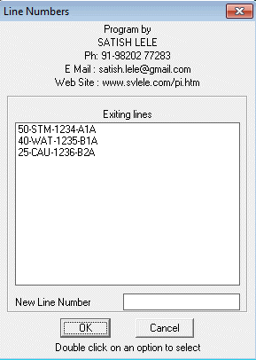
New Line Number: The existing lines are shown in the list box. We can add new lines to the box by typing in New Line Number and select add. New layer is created, and New Line Number is displayed in list box.
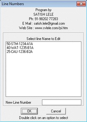
Edit Line Number : To edit an existing line number, we select a line number from list box, enter a new line number and select edit line number. The old number in list box is replaced by new number.
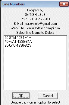
Delete Line Number : To delete an existing line number, we select a line number from list box, and existing Line Number is deleted.
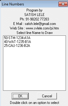
Draw Line : We can draw lines on a particular layer using this option. For this we have to either select a line number from list box, or type in a new line number. Lines will be drawn on that layer. Subsequently when valves and fitting are put in, these are put on this layer.
Dialog Box to insert Instruments : We can insert Instruments in the lines. We select an Instrument to be inserted. We are then asked to select where it is to be inserted.
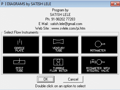
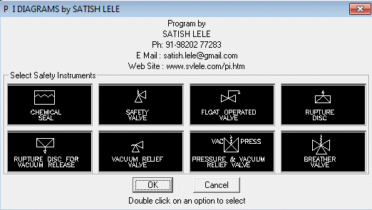
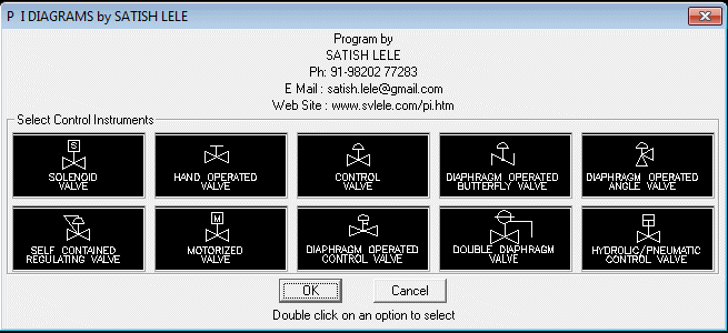
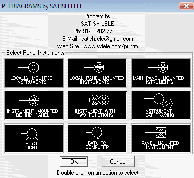
Dialog Box to insert valves : To insert a valve in a line, we select a valve to be inserted. We are then asked to select a line at left insertion point on that line. The line is cut and valve is inserted in the line. Valve is put on the layer of the line.
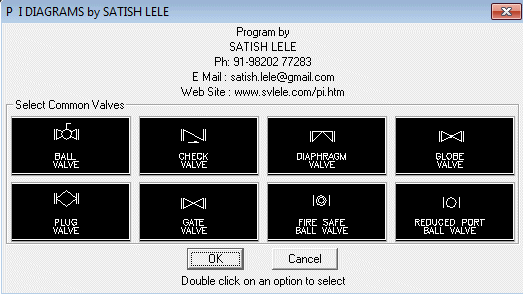
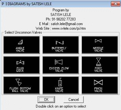
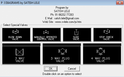
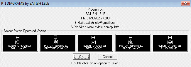
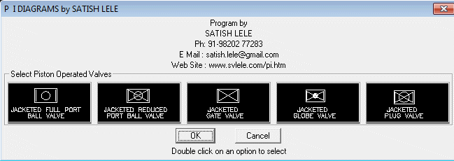
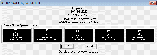
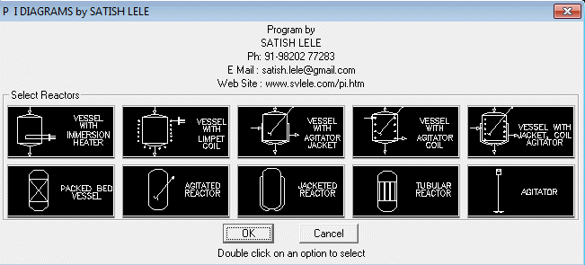
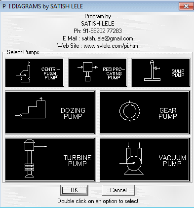
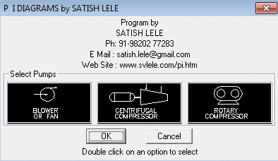
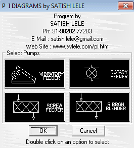
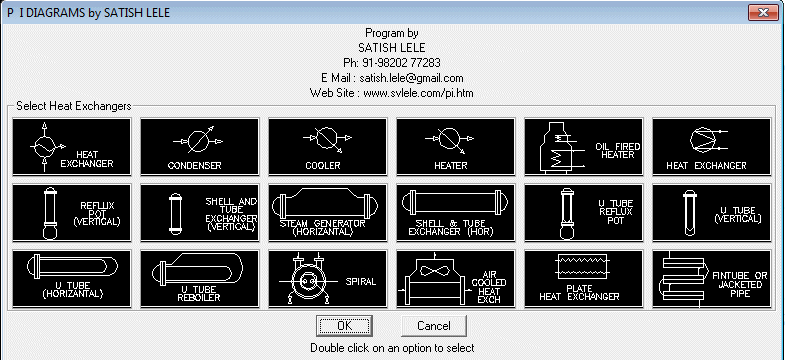
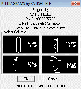
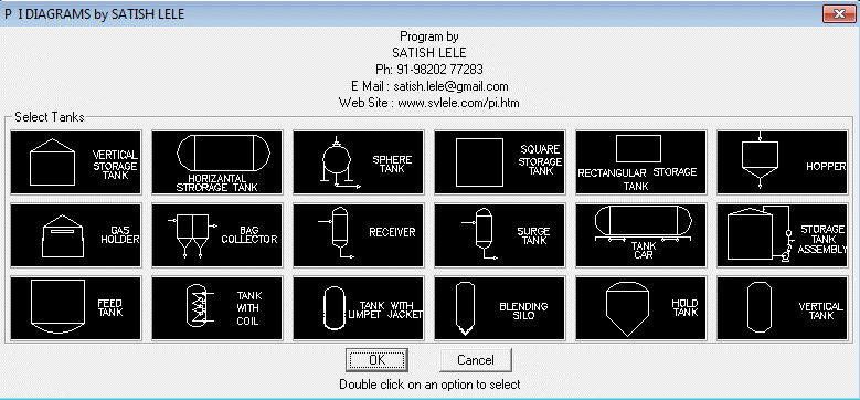
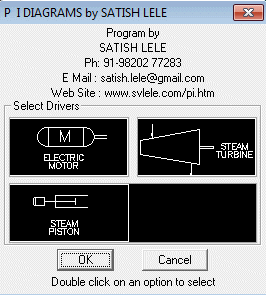
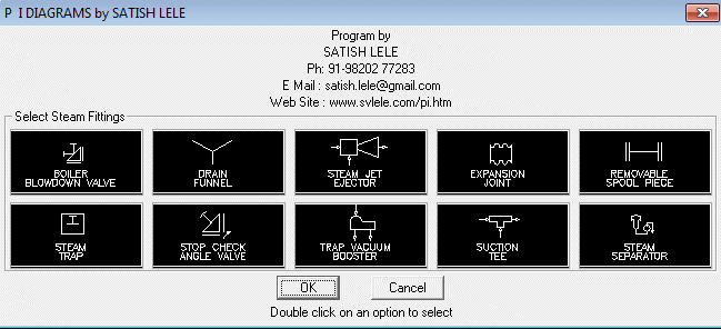
Dialog Box to insert Steam Fittings : We can insert Steam Fittings in the drawing. We select a Steam Fittings to be inserted. We are then asked to select a line at left insertion point where Steam Fitting is to be inserted. Steam Fittings is put on the layer of the line.
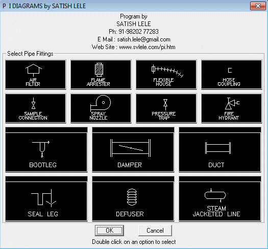
Dialog Box to insert Pipe Fittings : We can insert Pipe Fittings in the drawing. We select a Pipe Fitting to be inserted. We are then asked to select a line at left insertion point where Pipe Fitting is to be inserted. Pipe Fitting is put on the layer of the line.
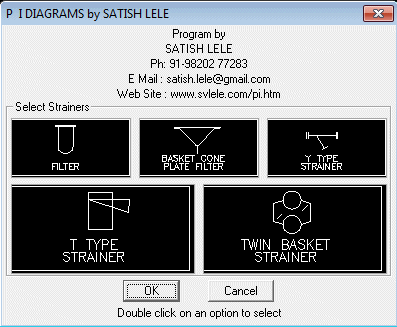
Dialog Box to insert Strainers : We can insert strainers in the drawing. We select a strainer to be inserted. We are then asked to select a line at left insertion point where strainer is to be inserted. Strainer is put on the layer of the line.
 Trial programs are full scale programs without option to insert Valves.
| My programs run well in in these inexpensive CAD Programs. Download Trial Programs of either BricksCAD or ProgeCAD or IntelliCAD or Draftsight or CADLogic or ZWCAD or FreeCAD to check usefulness of my packages. |

