 |
 |
 |
Satish Lele leleequip@gmail.com |
I offer Design and Drawing program which Designs and Draws a detailed drawing of Zero Hold up Filter, with user friendly dialog boxes, which is an add-on for any inexpensive CAD program like BricksCAD Lite, ProgeCAD, IntelliCAD, Draftsight, CADLogic, ZWCAD or FreeCAD for Designing and Developing GA drawing for Zero Hold up Filter. The Program for Design and Drawing of Zero Hold up Filter asks for some parameters and designs the basic parameters of Zero Hold up Filter. It writes all these in a text file which can be submitted as design criteria. Program for Design and Drawing of Zero Hold up Filter then draws the GA drawing and components. Program for Design and Drawing of Zero Hold up Filter gives all minor details (even weight of each component and total weight) at Quotation Stage itself and this helps to quote in most competitive manner.
- Information required for Design and Drawing of Filter
- Type of Zero Hold up Filter: Vertical Cylindrical
- Diameter of Filter Plate
- Number of plates
 to See Drawing in pdf Format
 I can offer this type of detailed drawing. Charges for Drawing of Filter: US$ 40 OR
  Program of Drawing of Filter is for sale:
Original Price US$ 300 OR
Special Price: US$ 250 OR
|
The Program for Design and Drawing of Zero Hold up Filter asks for parameters in the following dialog boxes, and based on these values, designs and draws. 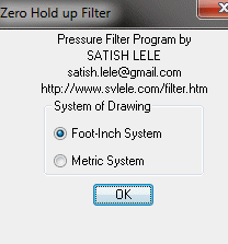 You can draw either in Foot-Inch units or in Metric Units. In Metric system it asks for all values in millimeters, and drawing will be to scale in Millimeters. In Foot-inch systems it asks for all values in Foot-inch, and drawing will be to scale in Foot and Inches.  You have three options. If you do not know the size and number of plates, you can use the Plate Sizing option. If you know the size and number of plates, you can use the Drawing option. If you use quit option, program will end.  If you select the Plate Sizing option, you can enter Liquid flow rate in US Gallons per hour and Total Cake Volume in Cubic Feet. Program will calculate appropriate size and number of plates. 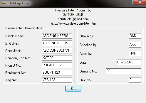 You can enter the data generally entered in Title Block. Current date is automatically displayed. Drawing number will be same as that entered earlier. The drawing will be saved with this number. 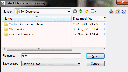 A Dialogbox then asks you to enter name of drawing and folder in which it is to be located. 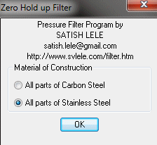 You can select material of construction for Filter. 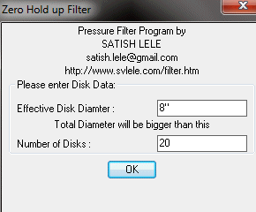 You can select Effective Diameter of Disk, height of disk and Number of Disks from Dialog Box. 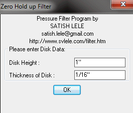 You can edit Your Input values for Filter Plate in edit boxes. Program suggests shell sizes. 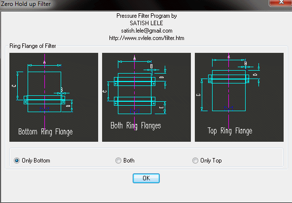 You can number of Flange Rings. Generally it is at Bottom, but you can select Top or Both.  You can a Dished End at Top or a Flat End. 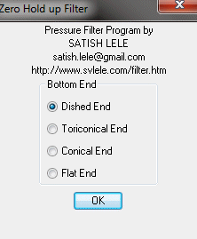 You can a Dished End, or a Toriconical end, or Conical end or a Flat End, at Bottom. 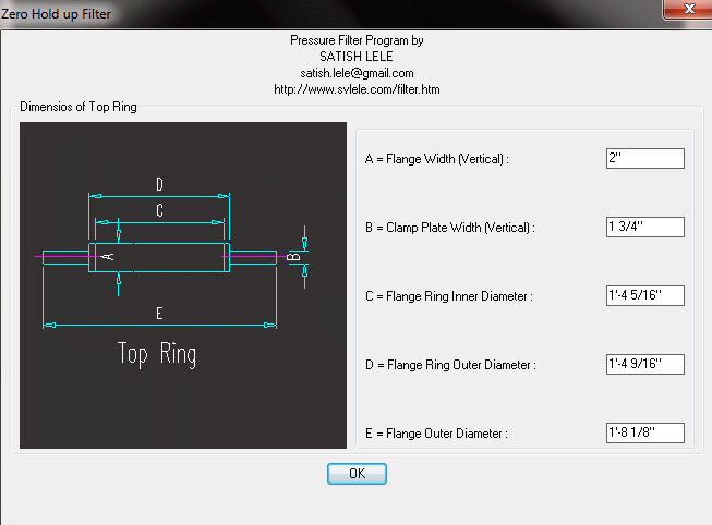 Dimensions of Top Ring Flange are calculated and shown. You can edit these if you wish. 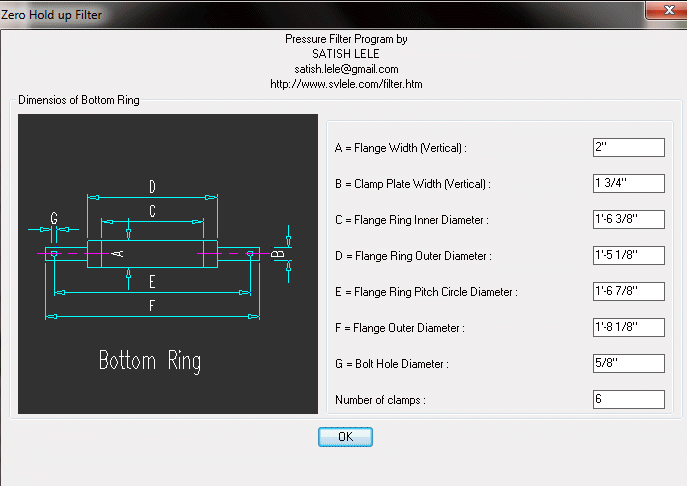 Dimensions of Bottom Ring Flange are calculated and shown. You can edit these if you wish. 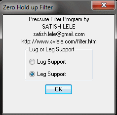 You can select support for filter. It can be Leg Support or Lug Supports. 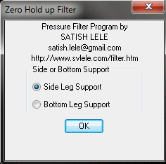 You can select leg support for filter. It can be Side Leg Support or Bottom Leg Supports.  You can select Type and size of bottom support. 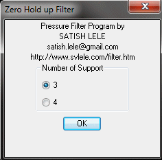 You can select number of leg support for filter. It can be 3 or 4 Leg Supports. 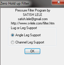 You can select number leg supports of Angle or Channel. 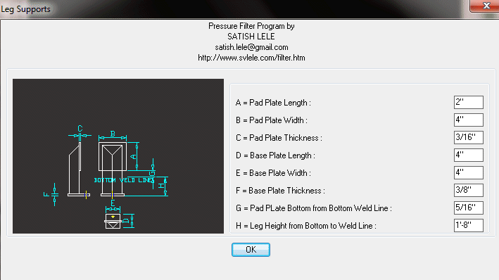 If you select Angle, it will indicate dimensions of Angle. 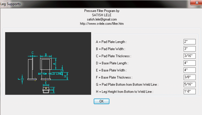 If you select Channel, it will indicate dimensions of Channel. 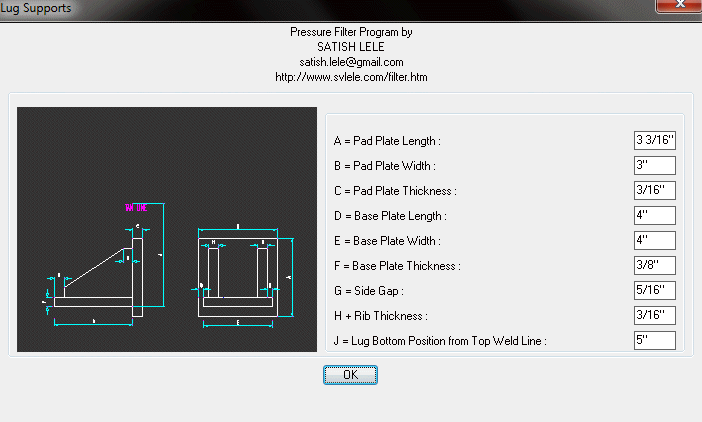 If you select Lugs, it will indicate dimensions of Lugs.  If you select Bottom Supports, you can select either Angle Channel or Pipe supports. 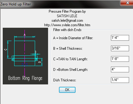 Based on the diameter of Filter Plates and Nunber of Filter Plates, it will show dimensions of the Filter. 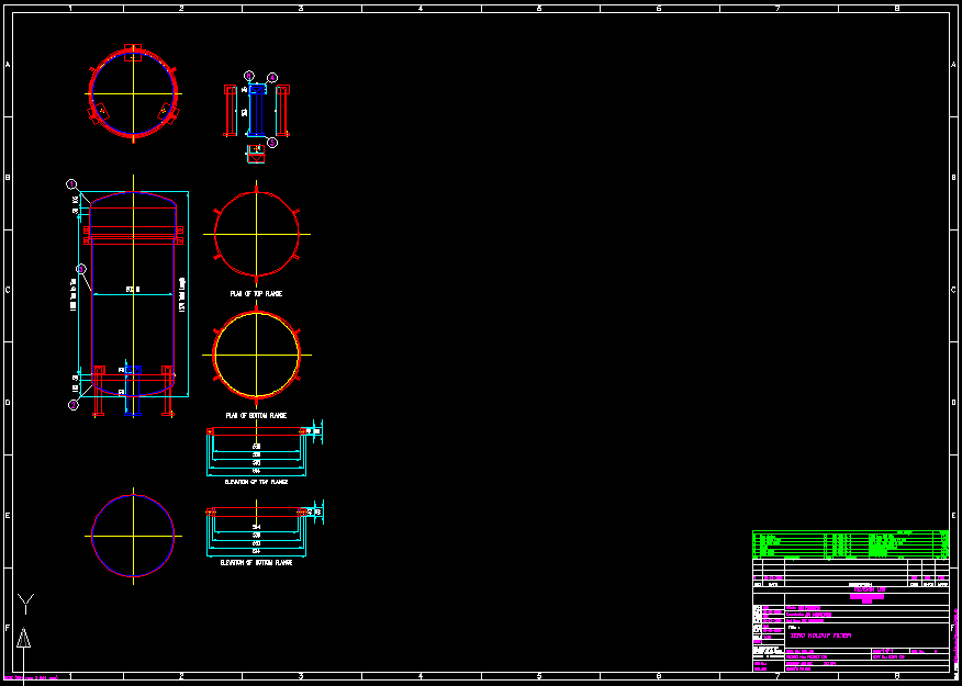 The drawing will be saved with the name given earlier in the folder mentioned.  to Download Trial Program to Download Trial Program |
 to Download Trial Program
 to View Details in Foot Inch units.
| Dia of Plate | No. of Plate | Filter Area m2 | Cake Cap Liters |
Flow rate Liters / Hr |
Size of Pump NB mm | Pump Motor |
| 8" | 6 8 |
0.220 0.280 |
5.0 6.3 |
600 800 |
15 15 |
1 HP 1 HP |
| 14" | 8 10 12 |
0.82 1.0 1.85 |
24.75 30.25 37.75 |
1500 1700 1900 |
25 25 25 |
2 HP 2 HP 2 HP |
| 18" | 10 12 15 24 |
1.65 1.95 2.40 3.75 |
55 65 80 125 |
4000 4600 5500 8200 |
40 40 40 40 |
3 HP 3 HP 3 HP 3 HP |
| 24" | 15 18 24 |
4.2 5.0 6.6 |
145 170 225 |
7000 8500 12500 |
50 50 50 |
5 HP 5 HP 5 HP |
 Agitator / Mixer Program
