 |
Satish Lele lelepiping@gmail.com |
View this page as YouTube Video Presentation
Plants on tidal waters (using water from the tides or sea) have a special problem in the construction of the cooling water system and in avoiding recirculation of the cooling water from the outlet back to the intake. In many plants, the intakes and outlets are separated by as much as 3 kilometers.
In tidal waters, the water flows in one direction for some time and in another direction for some time Therefore it requires special arrangements for the change in flow direction. Stations taking water from river or tidal sources usually have the ends of both suction and discharge pipes submerged below the lowest recorded tidal level. The water circulation system will operate at all times and at all states of tide if the distance between the lowest level and highest point of the circulation water system does not exceed 10 meters.
- The size of the cooling towers can be reduced where the site area is limited.
- The quantity of cooling water required is reduced as re-circulation is eliminated.
- The turbine plant efficiency is increased.
- This system should be adopted only when there is a possibility of recirculation and it is necessary to meet the requirements of fisheries board.
Cooling Towers: Cooling towers are heat removal devices used to transfer process waste heat to the atmosphere. Cooling towers may either use the evaporation of water to remove process heat and cool the working fluid to near the wet-bulb air temperature. Closed circuit dry cooling towers, rely solely on air to cool the working fluid to near the dry-bulb air temperature.

There are two main types of natural draft towers:
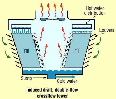
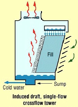
- Cross flow tower: air is drawn across the falling water and the fill is located outside the tower.
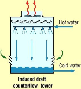
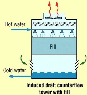
- Counter flow tower: air is drawn up through the falling water and the fill is therefore located inside the tower, although design depends on specific site conditions.
Mechanical draft towers are available in a large range of capacities. Towers can be either factory built or field erected. Concrete towers are only field erected. Many towers are constructed so that they can be grouped together to achieve the desired capacity. Thus, many cooling towers are assemblies of two or more individual cooling towers or cells. The number of cells they have, e.g., a eight-cell tower, often refers to such towers. Multiple cell towers can be lineal, square, or round depending upon the shape of the individual cells and whether the air inlets are located on the sides or bottom of the cells.
Common applications include cooling the circulating water used in oil refineries, petrochemical and other chemical plants, thermal power stations and HVAC systems for cooling buildings.
Cooling towers vary in size from small roof-top units to very large hyperboloid structures that can be up to 200 meters tall and 100 meters in diameter, or rectangular structures that can be over 40 meters tall and 80 meters long. The hyperboloid cooling towers are often associated with power plants, although they are also used to some extent in some large chemical and other industrial plants. Although these large towers are very prominent, the vast majority of cooling towers are much smaller, including many units installed on or near buildings to discharge heat from air conditioning.
Frame and casing: Most towers have structural frames that support the exterior enclosures (casings), motors, fans, and other components. With some smaller designs, such as some glass fiber units, the casing may essentially be the frame.
Wooden towers are still available, but many components are made of different materials, such as the casing around the wooden framework of glass fiber, the inlet air louvers of glass fiber, the fill of plastic and the cold-water basin of steel. Many towers (casings and basins) are constructed of galvanized steel or, where a corrosive atmosphere is a problem, the tower and/or the basin are made of stainless steel. Larger towers sometimes are made of concrete. Glass fiber is also widely used for cooling tower casings and basins, because they extend the life of the cooling tower and provide protection against harmful chemicals.
Fill: Most towers employ fills (made of plastic or wood) to facilitate heat transfer by maximizing water and air contact. Plastics are widely used for fill, including PVC, polypropylene, and other polymers. When water conditions require the use of splash fill, treated wood splash fill is still used in wooden towers, but plastic splash fill is also widely used. Because of greater heat transfer efficiency, film fill is chosen for applications where the circulating water is generally free of debris that could block the fill passage ways. There are two types of fill
- Splash fill: water falls over successive layers of horizontal splash bars, continuously breaking into smaller droplets, while also wetting the fill surface. Plastic splash fills promote better heat transfer than wood splash fills.
- Film fill: consists of thin, closely spaced plastic surfaces over which the water spreads, forming a thin film in contact with the air. These surfaces may be flat, corrugated, honeycombed, or of other patterns. The film type fill is more efficient and provides same heat transfer in a smaller volume than the splash fill.
Drift eliminators: These capture water droplets entrapped in the air stream that otherwise would be lost to the atmosphere.
Air inlet: This is the point of entry for the air entering a tower. The inlet may take up an entire side of a tower (cross-flow design) or located low on the side or at the bottom of the tower (counter-flow design).
Louvers: Generally, cross-flow towers have inlet louvers. The purpose of louvers is to equalize air flow into the fill and retain the water within the tower. Many counter flow tower designs do not require louvers.
Nozzles: These spray water to wet the fill. Uniform water distribution at the top of the fill is essential to achieve proper wetting of the entire fill surface. Nozzles can either be fixed and spray in a round or square patterns, or they can be part of a rotating assembly as found in some circular cross-section towers. Plastics are also widely used for nozzles. Many nozzles are made of PVC, ABS, polypropylene, and glass-filled nylon.
Fans: Both axial flow (propeller type) and centrifugal fans are used in towers. Generally, propeller fans are used in induced draft towers and both propeller and centrifugal fans are found in forced draft towers. Depending upon their size, the type of propeller fans used, is either fixed or variable pitch. A fan with non-automatic adjustable pitch blades can be used over a wide kW range because the fan can be adjusted to deliver the desired air flow at the lowest power consumption. Automatic variable pitch blades can vary air flow in response to changing load conditions. Aluminum, glass fiber and hot-dipped galvanized steel are commonly used as fan materials. Centrifugal fans are often fabricated from galvanized steel. Propeller fans are made from galvanized steel, aluminum, or molded glass fiber reinforced plastic.
- Selecting the right cooling tower (because the structural aspects of the cooling tower cannot be changed after it is installed)
- Fills
- Pumps and water distribution system
- Fans and motors
-
Selecting the right cooling towers: Once a cooling tower is in place it is very difficult to significantly improve its energy performance. A number of factors influence on the cooling tower�s performance and should be considered when choosing a cooling tower: capacity, range, approach, heat load, wet bulb temperature, and the relationship between these factors.
Capacity: Heat dissipation (in kCal/hour) and circulated flow rate (m3/hr) are an indication of the capacity of cooling towers. However, these design parameters are not sufficient to understand the cooling tower performance. For example, a cooling tower sized to cool 4,540 m3/hr through a 13.9oC range might be larger than a cooling tower to cool 4,540 m3/hr through 19.5oC range. Therefore other design parameters are also needed.
Range: Range is determined not by the cooling tower, but by the process it is serving. The range at the exchanger is determined entirely by the heat load and the water circulation rate through the exchanger and going to the cooling water. The range is a function of the heat load and the flow circulated through the system:
Range oC = Heat load (in kCal/hour) / Water circulation rate (l/hour)
Cooling towers are usually specified to cool a certain flow rate from one temperature to another temperature at a certain wet bulb temperature. For example, the cooling tower might be specified to cool 4,540 m3/hr from 48.9oC to 32.2oC at 26.7oC wet bulb temperature.
Approach: As a general rule, the closer the approach to the wet bulb, the more expensive the cooling tower due to increased size. Usually a 2.8oC approach to the design wet bulb is the coldest water temperature that cooling tower manufacturers will guarantee. When the size of the tower has to be chosen, then the approach is most important, closely followed by the flow rate, and the range and wet bulb would be of lesser importance.Approach (5.5oC) = Cold-water temperature 32.2oC � Wet bulb temperature (26.7oC) Heat load: The heat load imposed on a cooling tower is determined by the process being served. The degree of cooling required is controlled by the desired operating temperature of the process. In most cases, a low operating temperature is desirable to increase process efficiency or to improve the quality or quantity of the product. However, in some applications (e.g. internal combustion engines) high operating temperatures are desirable. The size and cost of the cooling tower increases with increasing heat load. Purchasing undersized equipment (if the calculated heat load is too low) and oversized equipment (if the calculated heat load is too high) is something to be aware of. Process heat loads may vary considerably depending upon the process involved and are therefore difficult to determine accurately. On the other hand, air conditioning and refrigeration heat loads can be determined with greater accuracy.
Wet bulb temperature: Wet bulb temperature is an important factor in performance of evaporative water cooling equipment, because it is the lowest temperature to which water can be cooled. For this reason, the wet bulb temperature of the air entering the cooling tower determines the minimum operating temperature level throughout the plant, process, or system. The following should be considered when pre-selecting a cooling tower based on the wet bulb temperature:- Theoretically, a cooling tower will cool water to the entering wet bulb temperature. In practice, however, water is cooled to a temperature higher than the wet bulb temperature because heat needs to be rejected from the cooling tower.
- A pre-selection of towers based on the design wet bulb temperature must consider conditions at the tower site. The design wet bulb temperature also should not be exceeded for more than 5 percent of the time. In general, the design temperature selected is close to the average maximum wet bulb temperature in summer.
- Confirm whether the wet bulb temperature is specified as ambient (the temperature in the cooling tower area) or inlet (the temperature of the air entering the tower, which is often affected by discharge vapors recirculated into the tower). As the impact of recirculation cannot be known in advance, the ambient wet bulb temperature is preferred.
- Confirm with the supplier if the cooling tower is able to deal with the effects of increased wet bulb temperatures.
- The cold-water temperature must be low enough to exchange heat or to condense vapors at the optimum temperature level. The quantity and temperature of heat exchanged can be considered when choosing the right size cooling tower and heat exchangers at the lowest costs.
- The inlet water temperature is increased (and the cold-water temperature at the exit remains the same). In this case it is economical to invest in removing the additional heat.
- The exit water temperature is decreased (and the hot water temperature at the inlet remains the same). In this case the tower size would have to be increased considerably because the approach is also reduced, and this is not always economical.
- Each kg of air entering the tower at a wet bulb temperature of 21.1oC contains 18.86 kCal. If the air leaves the tower at 32.2oC wet bulb temperature, each kg of air contains 24.17 kCal. At an increase of 11.1oC, the air picks up 12.1 kCal per kg of air.
- Each kg of air entering the tower at a wet bulb temperature of 26.67oC contains 24.17 kCals. If the air leaves at 37.8oC wet bulb temperature, each kg of air contains 39.67 kCal. At an increase of 11.1oC, the air picks up 15.5 kCal per kg of air, which is much more than the first scenario.
- Fill media effect: In a cooling tower, hot water is distributed above fill media and is cooled down through evaporation as it flows down the tower and gets in contact with air. The fill media impacts energy consumption in two ways
- Electricity is used for pumping above the fill and for fans that create the air draft. An efficiently designed fill media with appropriate water distribution, drift eliminator, fan, gearbox and motor will therefore lead to lower electricity consumption.
- Heat exchange between air and water is influenced by surface area of heat exchange, duration of heat exchange (interaction) and turbulence in water effecting thoroughness of intermixing. The fill media determines all of these and therefore influences the heat exchange. The greater the heat exchange, the more effective the cooling tower becomes.
- Splash fill media: Splash fill media generates the required heat exchange area by splashing water over the fill media into smaller water droplets. The surface area of the water droplets is the surface area for heat exchange with the air.
- Film fill media: In a film fill, water forms a thin film on either side of fill sheets. The surface area of the fill sheets is the area for heat exchange with the surrounding air. Film fill can result in significant electricity savings due to fewer air and pumping head requirements.
- Low-clog film fills: Low-clog film fills with higher flute sizes were recently developed to handle high turbidity waters. Low clog film fills are considered as the best choice for sea water in terms of power savings and performance compared to conventional splash type fills.

- Pumps and water distribution system:
- Optimize cooling water treatment: Cooling water treatment (e.g. to control suspended solids, algae growth) is mandatory for any cooling tower independent of what fill media is used. With increasing costs of water, efforts to increase Cycles of Concentration (COC), by cooling water treatment would help to reduce make up water requirements significantly. In large industries and power plants improving the COC is often considered a key area for water conservation.
- Drift eliminators: It is very difficult to ignore drift problems in cooling towers. Nowadays most of the end user specifications assume a 0.02% drift loss. But thanks to technological developments and the production of PVC, manufacturers have improved drift eliminator designs. As a result drift losses can now be as low as 0.003 � 0.001%.
- Fans and motors: The purpose of a cooling tower fan is to move a specified quantity of air through the system. The fan has to overcome the system resistance, which is defined as the pressure loss, to move the air. The fan output or work done by the fan is the product of air flow and the pressure loss. The fan output and kW input determines the fan efficiency.
The fan efficiency in turn is greatly dependent on the profile of the blade. Blades include:- Metallic blades, which are manufactured by extrusion or casting processes and therefore it is difficult to produce ideal aerodynamic profiles.
- Fiber reinforced plastic (FRP) blades are normally hand molded which makes it easier to produce an optimum aerodynamic profile tailored to specific duty conditions. Because FRP fans are light, they need a low starting torque requiring a lower HP motor. The life of the gear box, motor and bearing is increased, and maintenance is easier.
Compressor: Of the reciprocating, rotary, and centrifugal compressors, the most popular among domestic or smaller power commercial refrigeration is the reciprocating. The reciprocating compressor is similar to an automobile engine. A piston is driven by a motor to "suck in" and compress the refrigerant in a cylinder. As the piston moves down into the cylinder (increasing the volume of the cylinder), it "sucks" the refrigerant from the evaporator. The intake valve closes when the refrigerant pressure inside the cylinder reaches that of the pressure in the evaporator. When the piston hits the point of maximum downward displacement, it compresses the refrigerant on the upstroke. The refrigerant is pushed through the exhaust valve into the condenser. Both the intake and exhaust valves are designed so that the flow of the refrigerant only travels in one direction through the system.
Condenser: The condenser removes heat given off during the liquefaction of vaporized refrigerant. Heat is given off as the temperature drops to condensation temperature. Then, more heat (specifically the latent heat of condensation) is released as the refrigerant liquefies. There are air-cooled and water-cooled condensers, named for their cooling medium. The more popular is the air-cooled condenser. These condensers consist of tubes with external fins. The refrigerant is forced through the condenser. In order to remove as much heat as possible, the tubes are arranged to maximize surface area. Fans are often used to increase air flow by forcing air over the surfaces, thus increasing the condenser capability to give off heat.
Evaporator: This is the part of the refrigeration system that is doing the actual cooling. Because its function is to absorb heat into the refrigeration system (from where you don't want it), the evaporator is placed in the area to be cooled. The refrigerant is let into and measured by a flow control device, and eventually released to the compressor. The evaporator consists of finned tubes, which absorbs heat from the air blown through a coil by a fan. Fins and tubes are made of metals with high thermal conductivity to maximize heat transfer. The refrigerant vaporizes from the heat it absorbs in the evaporator.
Flow control device (expansion valve): This controls the flow of the liquid refrigerant into the evaporator. Control devices usually are thermostatic, meaning that they are responsive to the temperature of the refrigerant.
Heat transfer depends on the properties of the refrigerant. Different refrigerants will obviously have different enthalpy values for a given state. In dealing with one specific refrigerant, the enthalpy values depend on the temperatures and pressures in the warm and cold regions. The surrounding temperature affects how well the refrigeration system is able to cool the enclosed region. Clearly, if the outside temperature is very hot (i.e. much above room temperature), the system may not be as successful in lowering the temperature of the enclosed region as it would at room temperature.
 to get all the information as a eBook
