 |
Satish Lele lelepiping@gmail.com |
View this page as YouTube Video Presentation
A large percentage of world's power generation is achieved using steam turbines. The advantage of power generation using steam turbines are: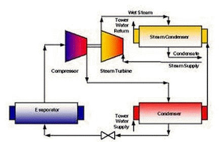
The steam turbine changes chemically stored energy into mechanical energy, too. It's called a heat-force engine. The steam turbine works similarly to the water turbine, which is known probably by everyone. Not water, but steam is used as working medium.
Turbine types: When people began to use water power to win mechanical work, they looked first for the best forms of impellers. Three types were established thereby and variations of them are used today in various applications, among other in steam turbines in power stations, as marine propellers, as compressors in gas turbines etc. These three types are introduced here:
Steam is produced in a steam boiler, which is heated in power stations by the burn of coal or gas or by atomic energy. Steam doesn't escape then, but after the passage through the turbine it is condensed in a condenser and then pushed back into the steam boiler again by a pump. This has the advantage that for example in nuclear power stations work- and cooling water are clearly separated.
Multi-level steam turbines: In modern steam turbines not only one impeller is propelled, but several being in a series. Between them idlers are situated, which don't turn. The gas changes its direction passing an idler, in order to perform optimally work again in the next impeller. Turbines with several impellers are called multi-level. The principle was developed 1883 by Parsons. As you know, with the cooling gas expands. Therefore it is to be paid attention when building steam turbines to a further problem: With the number of passed impellers also the volume increases, which leads to a larger diameter of the impellers. Because of that, multi-level turbines are always conical.
Coupling of several turbines: In power stations today, different types of turbines are used in a series, e.g. one high pressure -, two medium- and four low pressure turbines. This coupling leads to an excellent efficiency (over 40%), which is even better than the efficiency of large diesel engines. This characteristic and the relatively favorable production make the steam turbine competition less in power stations. Coupled with a generator and fired by an atomic reactor, they produce enormously much electric current. The strongest steam turbines achieve today performances of more than 1000 megawatts.
Gas Turbine
- The physical properties of steam (used as energy source for the turbines) are predictable at various pressures & temperatures and are constant across the globe.
- The Steam turbine designs are scalable, and can be design to suit any application.
- A Steam turbine separates the energy source and electrical power generation, making it compatible with various sources of fuels as feedstock (Coal, biomass, Municipal Waste, Gas), unlike a gas turbine, gas engine, diesel sets etc.
- Combined heat and power can be handled by steam turbines effectively, making it a widely used mode of power generation in process industry.
- By virtue of its operational characteristics (starting time and reliability) these turbines suits better, catering to the base load operation in modern power systems.

The steam turbine changes chemically stored energy into mechanical energy, too. It's called a heat-force engine. The steam turbine works similarly to the water turbine, which is known probably by everyone. Not water, but steam is used as working medium.
Turbine types: When people began to use water power to win mechanical work, they looked first for the best forms of impellers. Three types were established thereby and variations of them are used today in various applications, among other in steam turbines in power stations, as marine propellers, as compressors in gas turbines etc. These three types are introduced here:
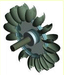
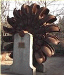
- The pelton turbine: The pelton turbine (also free-jet turbine) was invented 1880 by L.A. Pelton. It possesses spoon-shaped shovels, the jet hits the impeller tangentially, gets divided by the two shovels and transfers an impulse. The pelton turbine is used in storage power stations with downward gradients up to 2000 meters and can contain up to 6 nozzles.
- The francis turbine: The reaction turbine invented by J.B. Francis 1849 is hit by the jet almost axially (toward the axle) and radially (away from the center). The rotor blades can be adjusted, in order to ensure an even run. It looks similar to the type shown below as Steam turbine.
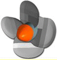
- The Kaplan turbine: The Kaplan turbine, developed around 1915 by the Austrian V. Kaplan, looks like a marine propeller. The jet is led thereby axially on the freely adjustable shovel pages.
Steam is produced in a steam boiler, which is heated in power stations by the burn of coal or gas or by atomic energy. Steam doesn't escape then, but after the passage through the turbine it is condensed in a condenser and then pushed back into the steam boiler again by a pump. This has the advantage that for example in nuclear power stations work- and cooling water are clearly separated.
Multi-level steam turbines: In modern steam turbines not only one impeller is propelled, but several being in a series. Between them idlers are situated, which don't turn. The gas changes its direction passing an idler, in order to perform optimally work again in the next impeller. Turbines with several impellers are called multi-level. The principle was developed 1883 by Parsons. As you know, with the cooling gas expands. Therefore it is to be paid attention when building steam turbines to a further problem: With the number of passed impellers also the volume increases, which leads to a larger diameter of the impellers. Because of that, multi-level turbines are always conical.
Coupling of several turbines: In power stations today, different types of turbines are used in a series, e.g. one high pressure -, two medium- and four low pressure turbines. This coupling leads to an excellent efficiency (over 40%), which is even better than the efficiency of large diesel engines. This characteristic and the relatively favorable production make the steam turbine competition less in power stations. Coupled with a generator and fired by an atomic reactor, they produce enormously much electric current. The strongest steam turbines achieve today performances of more than 1000 megawatts.
Gas turbines are a type of internal combustion (IC) engine in which burning of an air-fuel mixture produces hot gases that spin a turbine to produce power. It is the production of hot gas during fuel combustion, not the fuel itself that the gives gas turbines the name. Gas turbines can utilize a variety of fuels, including natural gas, fuel oils, and synthetic fuels. Combustion occurs continuously in gas turbines, as opposed to reciprocating IC engines, in which combustion occurs intermittently.
How Do Gas Turbines Work?: Gas turbines are comprised of three primary sections mounted on the same shaft: the compressor, the combustion chamber (or combustor) and the turbine. The compressor can be either axial flow or centrifugal flow. Axial flow compressors are more common in power generation because they have higher flow rates and efficiencies. Axial flow compressors are comprised of multiple stages of rotating and stationary blades (or stators) through which air is drawn in parallel to the axis of rotation and incrementally compressed as it passes through each stage. The acceleration of the air through the rotating blades and diffusion by the stators increases the pressure and reduces the volume of the air. Although no heat is added, the compression of the air also causes the temperature to increase.
The compressed air is mixed with fuel injected through nozzles. The fuel and compressed air can be pre-mixed or the compressed air can be introduced directly into the combustor. The fuel-air mixture ignites under constant pressure conditions and the hot combustion products (gases) are directed through the turbine where it expands rapidly and imparts rotation to the shaft. The turbine is also comprised of stages, each with a row of stationary blades (or nozzles) to direct the expanding gases followed by a row of moving blades. The rotation of the shaft drives the compressor to draw in and compress more air to sustain continuous combustion. The remaining shaft power is used to drive a generator which produces electricity. Approximately 55 to 65 percent of the power produced by the turbine is used to drive the compressor. To optimize the transfer of kinetic energy from the combustion gases to shaft rotation, gas turbines can have multiple compressor and turbine stages.
Because the compressor must reach a certain speed before the combustion process is continuous – or self-sustaining – initial momentum is imparted to the turbine rotor from an external motor, static frequency converter, or the generator itself. The compressor must be smoothly accelerated and reach firing speed before fuel can be introduced and ignition can occur. Turbine speeds vary widely by manufacturer and design, ranging from 2,000 revolutions per minute (rpm) to 10,000 rpm. Initial ignition occurs from one or more spark plugs (depending on combustor design). Once the turbine reaches self-sustaining speed – above 50% of full speed – the power output is enough to drive the compressor, combustion is continuous, and the starter system can be disengaged.
Gas Turbine Performance: The thermodynamic process used in gas turbines is the Brayton cycle. Two significant performance parameters are the pressure ratio and the firing temperature. The fuel-to-power efficiency of the engine is optimized by increasing the difference (or ratio) between the compressor discharge pressure and inlet air pressure. This compression ratio is dependent on the design. Gas turbines for power generation can be either industrial (heavy frame) or aero derivative designs. Industrial gas turbines are designed for stationary applications and have lower pressure ratios – typically up to 18:1. Aero derivative gas turbines are lighter weight compact engines adapted from aircraft jet engine design which operate at higher compression ratios – up to 30:1. They offer higher fuel efficiency and lower emissions, but are smaller and have higher initial (capital) costs. Aero derivative gas turbines are more sensitive to the compressor inlet temperature.
The temperature at which the turbine operates (firing temperature) also impacts efficiency, with higher temperatures leading to higher efficiency. However, turbine inlet temperature is limited by the thermal conditions that can be tolerated by the turbine blade metal alloy. Gas temperatures at the turbine inlet can be 1200ºC to 1400ºC, but some manufacturers have boosted inlet temperatures as high as 1600ºC by engineering blade coatings and cooling systems to protect metallurgical components from thermal damage.
Because of the power required to drive the compressor, energy conversion efficiency for a simple cycle gas turbine power plant is typically about 30 percent, with even the most efficient designs limited to 40 percent. A large amount of heat remains in the exhaust gas, which is around 600ºC as it leaves the turbine. By recovering that waste heat to produce more useful work in a combined cycle configuration, gas turbine power plant efficiency can reach 55 to 60 percent. However, there are operational limitations associated with operating gas turbines in combined cycle mode, including longer startup time, purge requirements to prevent fires or explosions, and ramp rate to full load.
 to get all the information as a eBook
