 |
Satish Lele lelepiping@gmail.com |
View Plant Layout as YouTube Video Presentation
Boundary: Boundary of the equipment is the term used in a processing facility, by an imaginary line that completely encompassed the defined site.
Dike: Dike is an earth or concrete wall providing a specified liquid retention capacity.
Diversion Wall: It is an earth or concrete wall which directs spills to a safe disposal area.
Fire Resistive: Fire resistance rating, as the time in minutes or hours, that materials or assemblies have withstand a fire exposure as established in accordance with the test of NFPA 251.
High Flash Stock: Those having a closed cup flash point of 55°C or over (such as heavy fuel oil, lubricating oils, transformer oils etc.). This category does not include any stock that may be stored at temperatures above or within 8°C of its flash point.
Low-Flash Stocks: Are those having a closed cup flash point under 55°C such as gasoline, kerosene, jet fuels, some heating oils, diesel fuels and any other stock that may be stored at temperatures above or within 8°C of it’s flash point.
Non-Combustible: Material incapable of igniting or supporting combustion.
Pipe Rack: The pipe rack is the elevated supporting structure used to convey piping between equipment. This structure is also utilized for cable trays associated with electric-power distribution and for instrument tray.
Plot Plan: The plot plan is the scaled plan drawing of the processing facility.
Sleepers: The sleepers comprise the grade-level supporting structure for piping between equipment for facilities, e.g., tank farm or other remote areas.
Tank Diameter: Where tank spacing is expressed in terms of tank diameter, the following criteria governs:
(a) If tanks are in different services, or different types of tanks are used, the diameter of the tank which requires the greater spacing is used.
(b) If tanks are in similar services, the diameter of the largest tank is used.
Tank Spacing: It is the unobstructed distance between tank shells, or between tank shells and the nearest edge of adjacent equipment, property lines, or buildings.
Toe Wall: It is a low earth, concrete, or masonry unit curb without capacity requirements for the retention of small leaks or spills.
Vessel Diameter: Where vessel spacing is expressed in terms of vessel diameter, the diameter of the largest vessel is used. For spheroids, the diameter at the maximum equator is used.
Vessel Spacing: It is the unobstructed distance between vessel shells or between vessel shells and nearest edge of adjacent equipment, property lines, or buildings.
Some Key Issues Related To Layout:
Terrain: In the first place, considerations should be given to the physical setting. It should not automatically be assumed that it is necessary to level the site. There may instead be ways that the process can take the advantage of whatever slopes are present.
With respect to terrain, assess should be made, whether, there is adequate space in general. If not, ingenuity will be required to meet such requirements as those for flares. Available space can help to govern whether the plant can be located on one floor or instead occupy several stories. The physical setting shall also be considered in light of the Transportation requirements for raw materials, products, wastes and supplies.
Safety and Environment:
- Familiarization with pertinent Environmental Regulations, (Local, National and International), and how they might change is essential period to conclusion of pre-project studies.
- Attention shall be given to the pertinent safety regulations, including health and welfare needs.
- Hazardous and flammable materials require special handling, which can take up layout space.
- If the process fluids are especially toxic, layout is affected by the need for close chemical sewers and other protection measures. Security requirements may require special layout design when the plant produces a high-value product.
- If a plant site is governed by particular building, piping, plumbing, electrical and other codes, these can affect plant layout. Similar governing standards and regulation in plant site affects the layout concept.
1. For operator access via a central aisle.
2. The need that the outlet sides of two lines of equipment (pumps, for instance) point toward each other so that they can be readily hooked to one common line.
Basic Considerations:
General
The plant layout shall be arranged to:
1. maximize safety.
2. prevent spread of fire.
3. Facilitate easy operation and maintenance.
4. Consider future expansion.
5. Economize project.
Blocking: The plant site shall be blocked in consideration of hazards attendant to plant operation in the area. All blocked areas shall be formed as square as possible by divided access roads and/or boundary lines.
Location and Weather: The plant layout shall be arranged in consideration of geographic location and weather in the region of the site.
Prevailing Wind: Where the prevailing wind is defined, the administration and service facilities and directly fired equipment, etc., shall not be located windward of process Units and storage tanks, etc.
Layout Indication: The basic requirements to be met in the appropriate diagram when making a piping and equipment layout are:
1. All equipment, ladders, structures, davits, trolley beams, shall be indicated.
2. All instruments shall be located and indicated.
3. All valves and hand wheel orientations shall be indicated.
4. Drip funnel locations for underground drains shall be indicated.
5. All electrical switch gear, lighting panels shall be indicated.
6. All sample systems shall be indicated.
Classification of Hazards: The plant layout shall be determined in consideration of classified hazardous areas.
Plant Layout:
Area Arrangement: Classified blocked areas, such as process areas, storage areas, utilities areas, administration and service areas, and other areas shall be decided on the bases of following factors:
1. Soil characteristics.
2. Main road, rail access ways, and jetty.
3. Location of pipelines to and from plant.
4. Direction of prevailing wind.
5. Local law and regulation which may affect the location of units and storage facilities.
6. Natural elevation for location of upstream / downstream units and equipment (such as feed and product storage tanks, wastewater plant, oil/ water separator, etc.) and arranged as follows:
- The process area shall be located in the most convenient place for operating the process Unit. The units shall be separated by roads. Major roads shall have minimum width of 10 m., with maximum length of 400 m. The minor roads shall have minimum width of 6 m. (Minor roads shall not be in an area classified as zone 0 or 1). A plant may contain one or several process units. Where any unit processes flammable fluids and may be operated independently (i.e. one unit may be shut down with others in operation). The minimum spacing between equipment on the two adjacent units shall be at least 20 m.
- The storage area shall be located as far as possible from buildings occupied by personnel at the site, but should be located near the process area for ready operation of the feed stocks and product run downs.
- The utilities area shall be located beside the process area for ready supply of utilities. Except where they are an integral part of a process unit, site utility units should be grouped together in an area classified as nonhazardous.
- Loading and unloading area shall be located on a corner of the site with capable connection to public road directly, for inland traffics. Loading / unloading areas for road transport shall have adequate space to provide access for filling, parking and maneuvering. A drive through rack arrangement is preferred. The loading and unloading facilities should be downwind or crosswind from process units and sources of ignition, based on the direction of prevailing wind. For marine transportation, the area shall be located on the seaside or riverside in the plant site.
- The administration and service area shall be located at a safe place on the site in order to protect personnel from hazards. It shall preferably be located near the main gate alongside the main road of the plant.
- Flare and burn pit shall be located at the end of the site with sufficient distance to prevent personnel hazard.
- Waste water treating Unit shall be located near at the lowest point of the site so as to collect all of effluent streams from the processing Unit.
- The process Unit to which the feed stock is charged first, shall be located on the side near the feed stock tanks, to minimize the length of the feed line.
- The process Unit from which the final product(s) is (are) withdrawn, shall be located on the side near the products tanks to minimize the length of the product run-down line.
- Process Units, in which large quantities of utilities are consumed, should be preferably located on the side near the utility center.
- Security fence:
- All sites (plants or complex) shall be within a security fence.
- The minimum space between security fence and units’ boundary shall be 20 m, and between security fence and equipment shall be 30 m.
- In case of special units such as flammable material storage with vapor release and toxic materials, minimum space shall be at least 60 m from site boundaries adjacent to centers of population (domestic, work or leisure ).
- Fire water pumps and equipment shall be sufficiently remote from processing, storage and loading areas, where a major fire could occur.
Pipe racks and Sleepers:
1. In general, pipe racks for process Units and pipe sleepers for the off-site facilities shall be considered as the principals support of the pipe way. Run pipe lines overhead should be grouped in pipe racks in a systematic manner.
2. Pipe rack runs oriented in the same direction shall be at consistent elevations. Pipe rack runs oriented opposite to these runs shall be at other elevations to accommodate crossing of lines at pipe racks junctions and to accommodate branch line intersections.
3. Single level pipe racks are preferred, if more than one level is required, the distance between levels oriented in the same direction shall be adequate for maintenance but not less than 1.25 meters.
4. Maximum pipe rack widths shall be 10 m. If widths larger than 10 m are required, the pipe rack shall be designed to be of two stages. Actual widths shall be 110% of the required widths or the required widths plus 1m. In cases where air fin coolers are to be placed on the pipe racks, the pipe rack widths shall be adjusted based on the length of the air coolers.
5. Avoid flat turns. When changing directions, change elevation.
6. Allow ample space for routing instrument lines and electrical conduit. Provide 25% additional space for future instrument lines and electrical conduit adjacent to that required.
7. Provide 20% additional space on the pipe rack for future piping. This space shall be continued and clear on each level for the full length of the rack. The width allocation may be split in two sections but not more than two.
8. Allow a continuous clear area of 4 meters high by 4 meters wide below main racks in process Units for maintenance access ways.
9. Pipe racks outside process areas shall have the following minimum overhead refinery/plant clearances: main roadway: 5 meters, access roads: 4.5 meters, railroads: 6.7 meters above top of rail.
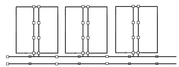
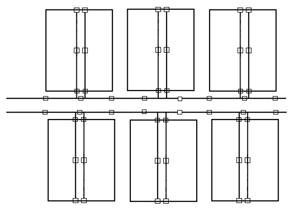
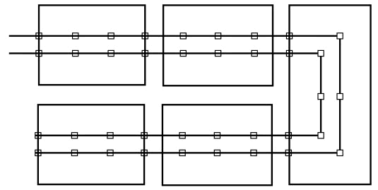
10.Typical layout of pipe rack, for process plants depending on the number of process Units incorporated and the process complexities are given in Figures with reference descriptions as follow:
- "Single Rack Type" layout, is suitable for small scale process complex consisting of two-three process Units. It is economical without requiring any large area.

- "Comb Type" layout is recommended for use in process, complex consisting of three or more process Units. "Single Rack Type" in this case will not be suitable since separate maintenance and utility administration in normal operation will be difficult because of the utility and flare line which are placed on the common rack.
- "Double Comb Type" layout is an expansion of the "Comb Type" which is recommended for the use in large scale process complexes where five to ten process Units are to be arranged. This layout, can be conveniently utilized.
- "U Type" layout is recommended to be used in case of process Units whose maintenance cannot be conducted separately, within the complex. This type can be regarded as an expansion of the "Single Rack Type". Even process complexes of this nature, can be regarded as one process Unit in the planning of their layout.
12.Overhead racks may contain more than one level. For steel pipe racks, the height of levels shall have one of the following elevations:
a. Main pipe racks : 4.60, 6.20, 7.80 m
b. Individual or secondary pipe rack: 3.80, 5.40, 7.00 m. In special cases for large size pipes or concrete pipe racks, the distance between the various floors may be increased.
13.Except for special cases, minimum width of pipe rack shall be 6 m. The width of pipe rack shall be designed to accommodate all pipes involved plus 20% space for future expansion or modification. Where the pipe rack supports air coolers, the preferred width shall be the width of air coolers.
14. In multi-level pipe racks, pipe carrying corrosive fluids shall be on the lower level, and utility lines should be at the upper floor. Large size or heavy weight pipes shall be located at the lower level and on extreme sides.
Layout of Control Room and Electrical Sub-Station
1. The control room and substation shall be located as close as possible to the plant equipment, maintaining a minimum distance from viewpoint of noise and safety requirements.
2. The control rooms, and substation shall be spaced at least 15 m from the nearest process equipment surface.
3. The control room and substation shall be located with consideration to convenience in daily operation.
4. The control room and substation shall be located from an economical standpoint so as to minimize the length of electrical and instrument cables entering and leaving therefore.
5. The control room shall be positioned so that the operator can command a view of the whole system which is under control. Large buildings, or equipment shall not be placed in front of the control room.
Fire Fighting Requirements
1. Each individual process Unit shall be provided with sufficient open spaces there around that, fire trucks can be run and operated thereat. The width of access way there to, shall be 6 meters minimum.
2. Process Units consisting of large hazardous material storage tanks should be located desirably in outer area in the complex site.
3. High-pressure gas lines shall not pass through a process area or run within 30 m of important structures or equipment without shutdown valve to insure that portions of piping within the process area can be isolated from the main gas line and depressurized in the event of an emergency. However, extensive use of shutdown valves may not be needed, since the increased complexity of the system will require a greater degree of preventive maintenance if unwarranted shutdowns are to be avoided. Shutoff valves, sometimes known as "station isolation valves", shall be provided on all gas and product pipelines into and out of the plant.
A bypass line with a normally shut valve may be required between plant inlet and discharge lines. All station isolation valves-and bypass valves, if any should be located at a minimum distance of 75 m but not more than 150 m from any part of the plant operations. Care should be taken in locating these valves so that they will not be exposed to damage by plant equipment or vehicular traffic.
4. At least two remote emergency shutdown stations, located at a minimum distance of 75m apart, shall be provided. Locate actuating points at least 30m from compressor buildings and high pressure gas lines. More than two shutdown stations may be required, depending on the size and complexity of a given plant. One of the actuating stations shall be located in the control room. It shall be distinctively marked and equipped with signs stating the proper method of actuation in the event of an emergency.
5. Wastewater separators handling hydrocarbons should be spaced at least 30 m from process unit equipment handling flammable liquids and 60 m from heaters or other continuous sources of ignition. Preferably, wastewater separators should be located downgrade of process equipment and tanks.
6. Fire training areas are ignition sources when in use. Because of the smoke produced, they can also create a nuisance for the refinery and neighboring facilities. Fire training areas shall be 60 m from process unit battery limits, main control rooms, fired steam generators, fire pumps, cooling towers and all types of storage tanks. They shall also be 75 m from property boundaries, administration, shops, and similar buildings and from the main substation.
Building Requirements
1. Service buildings include offices, control rooms, laboratories, houses, shops, warehouses, garages, cafeterias and hospitals.
2. These structures and areas require protection of personnel from possible fires and explosions of major plant equipment and may require additional spacing from high risk facilities.
3. The service buildings shall be located near the entrance of the plant and be readily accessible to a public road or highway.
4. Spacing at refineries, petrochemicals, chemicals, and gas plants for buildings shall be in accordance with Insurance recommendation.
Access Requirements: Access ways within the plant shall be provided for maintenance, emergency case, and for fire fighting from the road around the plant. Piping system shall be laid in such a way to make possible passage of mobile equipment. Operating passageway between equipment or piping and adjacent equipment generally is 1050 mm minimum except when otherwise shown on drawings.
Minimum widths of access way shall be as follows:
1. Vehicular access ways within units: 4.0 m
2. Pedestrian access ways and elevated walkway: 1.2 m
3. Stairways and platforms: 0.8 m
4. Footpaths in tanks areas: 0.6 m
5. Maintenance access around equipment: 1m
6. Fire truck access way: 6m
Minimum headroom clearance for access ways shall be as follows:
1. Over railways or main road: 6.8 m
2. Over access roads for heavy trucks: 6 m
3. For passage of truck: 4 m
4. For passage of personnel: 2.1 m
5. Over fork-lift truck access: 2.7 m
Preparation of Plot Plan Drawing
The general plot plan drawing shall give the layout of the whole plant(s). It should be prepared in accordance with one of the following scales: 1:500, 1:1000, 1:2000.
The following items shall be shown in plot plan drawing:
1. Battery limits of complex (area boundary).
2. Plant geographical and conventional north.
3. Elevation, with regard to the nominal plant 0 (zero) elevation.
4. Coordinates of main roads, process units, utility units, buildings, storage tanks and main pipe rack.
5. Location of flares and burn pit.
6. Direction of prevailing wind.
Plant coordinates may be started from point N=0, and E= 0
Layout in Process Units:
1. In cases where process fluid is run by gravity head, elevated layouts must be considered. Unless there are any such limitations as indoor arrangement and confined locations, equipment shall be placed at grade as a rule except in cases where gravity flow is specifically required for any reason.
2. Since the directions of the incoming feed stocks, outgoing products and utility supply are determined on the overall plot plan, first the direction of the pipe rack in the Unit shall be decided.
3. Equipment shall be arranged to minimize piping runs (particularly, for large sized piping and alloy piping) as far as possible. Clear access ways having minimum width of 600 mm shall be provided for the operators access around equipment.
4. Large capacity storage tanks containing flammable and explosive fluids shall be located in outer areas as far as possible.
5. Space shall be allowed for the provision of future spare equipment. Consideration shall also be given to future plant expansion.
6. The drawing shall be prepared in one of the following scales: 1:1500, 1:1200.
7. The drawing shall show the following items:
a. Conventional North.
b. Coordinates of battery limits and roads.
c. Symbols for equipment and coordinates of their centerlines.
d. Finished floor elevation.
e. Equipment index list.
8. The area of any unit shall not exceed 20,000 m2, and the length of each side should not exceed 200 m.
9. For units processing flammable fluids, the central control building shall be adjacent to a road. It shall not be located in any area classified as zone 0 to 1.
Process Requirements:
1. Equipment shall be laid out along the flows on the process flow diagram.
2. Especially, the fractionators and the reboiler, condensers and overhead receivers shall be collectively located.
3. Gravity flow lines shall be laid out with consideration given to related elevations, so that their lengths will become minimum. Especially in the case of lines in which liquids will flow near at their boiling points, related equipment shall be located close to each other so that the lines need not be elevated.
4. Pieces of equipment which are to be connected by large-size piping or alloy piping shall be located close to each other.
5. Air coolers shall be laid out so that no heated air may be recirculated.
Safety Requirements:
1. All process equipment should be kept at least 15 meters from fired heaters. Exception are permitted for certain pieces of equipment where the heater in question is being used to heat the process flow of the equipment and where any leakage from the equipment would probably ignite instantly, thus no additional fire hazard. Such an exception is permitted when locating reactors on a reforming Unit (an example). Each exception must be individually investigated as to its potential hazards and must not violate any process practices in OGP plants and governing codes.
2. Locate fire heaters on the side of the process Unit from which the prevailing wind blows. This is done to blow gas away from the heaters instead of towards them. Fired equipment shall not be located in "Hazardous Area Classification". Generally, fired equipment shall be located at a distance of more than 15 meters from any sources of hazards (hot oil pumps, light end pumps, compressors etc.).
3. Emergency showers, if required in a certain process, should be located as near the hazard as possible and indicated in the Plot Plan.
4. Adequate and easy access and egress must be considered for not only safety, but operation and maintenance requirements.
5. Control rooms and their roadways shall not be located in hazardous area, classified in project specification; generally, they shall be located at a distance of more than 15 meters from the nearest equipment.
6. High pressure gas compressors shall be located at leeward locations.
7. Large-Capacity hazardous material storage tanks shall be located in outer areas as far as possible.
8. Pumps intended to handle flammable materials (which fall under the control of the hazardous area classification), shall be located on the following basis.
9. Fired heater stacks shall be located at such points that the performance of the air coolers and operators on tower tops may not be adversely affected by hot flue gas emitted through them: the directions of prevailing wind shall be taken into consideration in the determination of the stack locations.
A good piping layout is essential for proper handling of liquid products. Piping cost is generally 20 to 25% of project cost. There are 2 areas of Piping layouts.
Inside Battery Limit : This is piping inside process plant. Generally each floor is 4 meters high. Pipes should enter in the plant at 3 meters above floor level, at one or preferably at more locations. The pipes are laid along the wall or structural columns. This helps in supporting the pipe lines. There can be one or two layers of pipe lines inside the plant. The distance between two rows is such that branching above lower layer and below upper layer is possible. The branching distance depends on size of the pipe and length of the elbow. Steam pipe is placed near the wall. Pipes of higher diameter are then placed near the wall. Other pipes are placed as per gap table. The pipes may move one layer to other while change in direction.
Piping of Vapor Lines : When it originates from top of Reaction vessel, it rises up and connects to a condenser. There should be number of bends as possible, which allow the pipe to expand (while heating) or contract (while cooling). The line should have a slope towards reaction vessel, so as to drain all liquid to reaction vessel, when reactor is closed down. The pipe lines should not obstruct the agitator assembly on the top of the vessel. When it originates from top of Distillation Column, a loop is created at the top outlet of the column and then the line drops down. At lower end, 2 or 3 bends are provided, before it enters into condenser. Such flexibility is not required for pipe lines at ambient temperature.
How to create a Piping Layout Drawing : To create a drawing first put in drawing plan, the locations of columns at proper distance. Mark the columns in both the direction. Put beams of proper width. Cross mark the areas where no equipments are placed.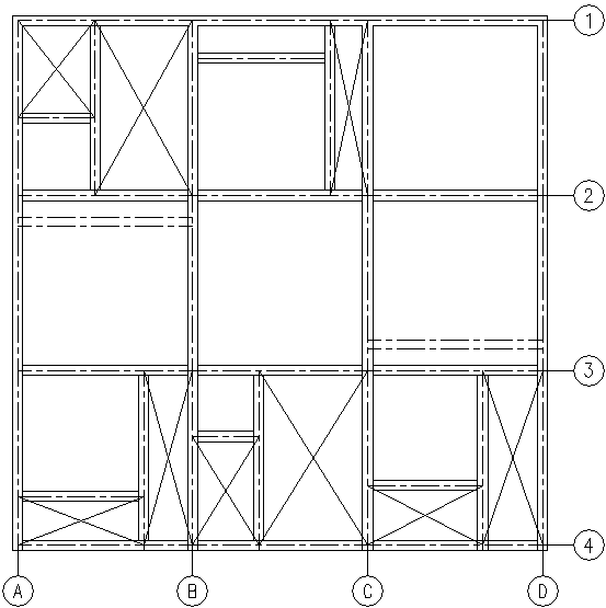
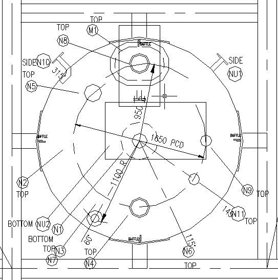
Place the equipments in proper location, showing all nozzles.
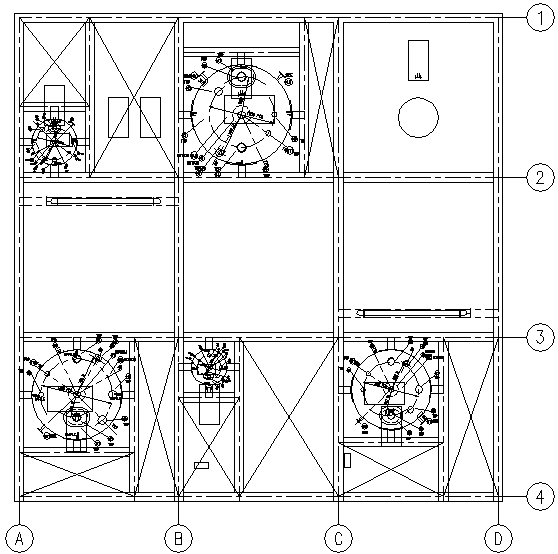
Typical details of one equipment.
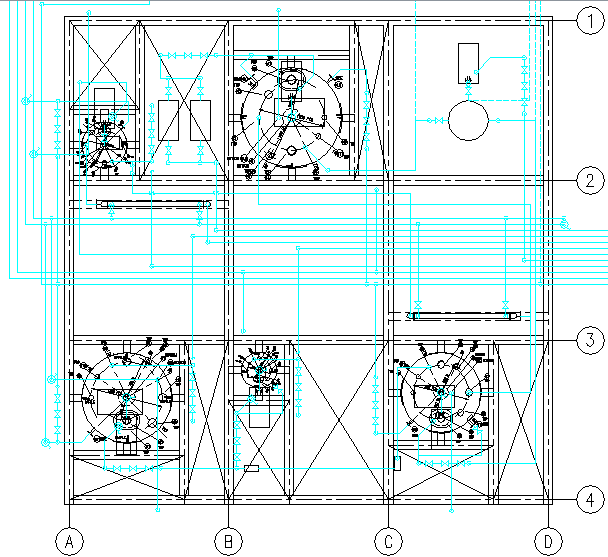
Utility lines are put in central bay which supply utilities to different equipments. Interconnecting piping is then drawn for each vessel. Proper gap is maintained between pipe lines.
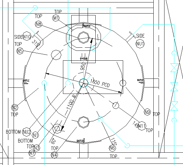
Typical Piping details of earlier equipment, which shows connections and steam control station.
Line numbers and elevation of each pipe line from floor level in marked on each line. Pipe lines arranged in such a way that a number of lines are at one elevation in one direction. In other direction, the pipe lines a placed 300 to 500 mm above or below the earlier level.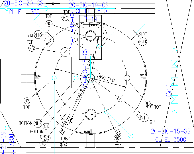
Outside Battery Limit : This is piping outside process plant, in storage and utility area. Some pipe lines carry raw materials to the process plant. Finished products are transported back to tank farm area, from process plant area by other pipe lines. These are laid on either:
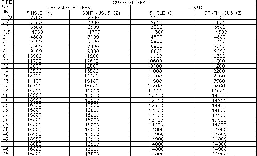
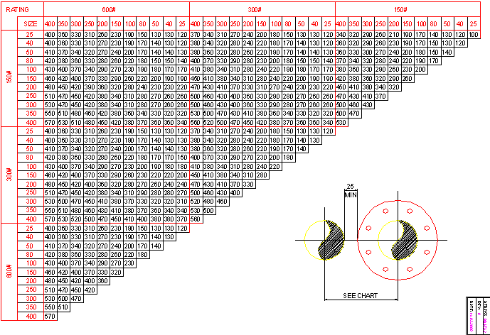
On Grade : This is generally around he storage tanks. Grade is made of a brick wall 300 mm high or a steel structure. If it is a wall, a steel rod is embedded on top of it. The pipes rest on the steel rod on wall. The distance between the two grade walls, or structures is decided by smallest pipe running on it. The distance between two pipes is decided by the spacing table.
Pipe Racks : When the pipes cross a number of roads, it is put on a pipe rack. The pipe rack is generally at such a height, that a truck carrying container can pass under it. Here, the distance between two pipes is decided by the spacing table.
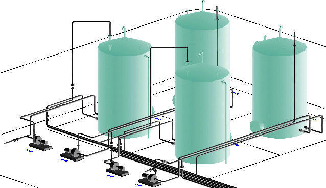
Method of placement of pipes on Grade or Pipe Rack : The storage tanks normally have dike wall around it. The pump suction piping is routed over the wall. The piping for the last tank is put in first. The pump suction line has a block valve on tank. It has a strainer near the pump. It then connects to the pump suction, through an optional block valve and an eccentric reducer. The distance between wall and pump suction should be at least 1 meter to accommodate these fittings. The discharge line of pump has block valve, followed by a check valve. A pressure indicator is located before the block valve. The horizontal pipe from pump, should not be located over the pump or motor. The pipe line is then placed on grade. Sufficient vacant space should be maintained for maintenance of the pump. The piping for subsequent tanks is placed in order. The gap between pipes, is fixed as per gap table based on pipe diameter and class. If another pipe is to be placed in between, all pipes are moved as per the gap required. The sequence of the pipes can be changed, when there is a change in direction. The steam pipes should be placed at one end.
To create a piping plan, place the equipments in proper location, showing all nozzles. Show dike walls around the tanks.
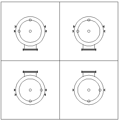
Pines are put on grade which supply utilities to different equipments. Interconnecting piping is then drawn for each vessel. Proper gap is maintained between pipe lines.
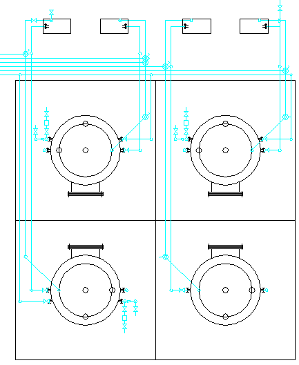
Line numbers and elevation of each pipe line from floor level in marked on each line. Pipe lines arranged in such a way that they not cross each other.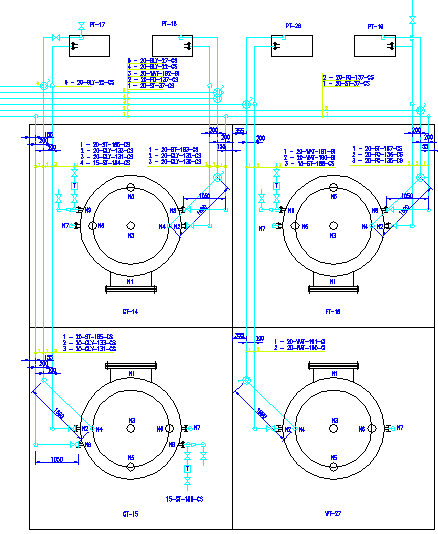
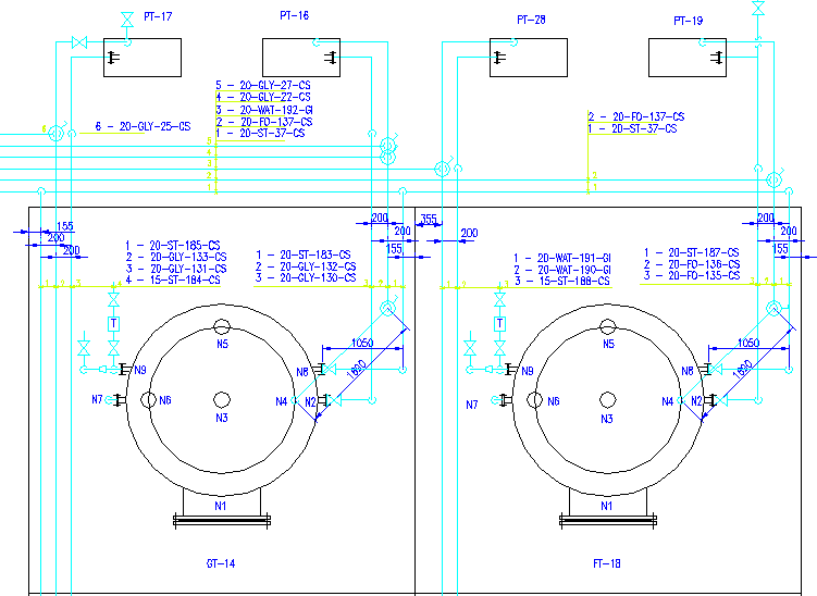
Typical details of two equipments.

View Piping Layout as YouTube Video Presentation
 to get all the information as a eBook
