 |
Satish Lele lelepiping@gmail.com |
View this page as YouTube Video Presentation
Pipes, fittings, valves, and accessories make up a plastic pressure pipe system.
Pipe: The range of pipe diameters for each pipe system does vary. However, the size ranges from 12 to 400 mm. Pipes are extruded and are generally available in: 3 m, 4 m, 5 m, and 6 m straight lengths and 25 m, 50 m, 100 m, and 200 m coils for LDPE and MDPE.
Plastic piping is used in various sectors including mining, building and industrial. Applications include: water and sewerage reticulation, drainage and discharge systems, construction, irrigation, mining, water, slurry, acid.
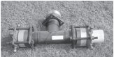
HDPE and PP range includes Compression Fittings and Saddles, Thermoplastic Valves and Fittings, Bends, T-pieces, Laterals, Spool Pieces, Manufactured Steel Saddles, Piping And Coils, Jointing Systems.
Polyethylene pipes have yielded excellent results when used in different mining applications. Owing to their high abrasion and corrosion resistance, ease of handling of installation and their high mechanical strength, they are ideal for:
Irrigating leaching piles Conveying acid and alkaline solutions, Concentrate pipelines (Reduction works and Drainage), Fire fighting installations, Drinking water lines, Chilled water lines, Compressed air lines, Ventilation ducting, Vacuum lines.
Fittings are molded and come in many sizes: tee 90° equal (straight and reducing), tee 45°, cross equal, elbow 90° (straight and reducing), elbow 45°, short radius bend 90° socket/coupler (straight and reducing), union, end caps, reducing bush, and stub, full face, and blanking flanges.
Valves are moulded and also come in many types: ball valve (also multi port), butterfly valve, spring-, ball-, and swing-check non-return valves, diaphragm valve, knife gate valve, globe valve and pressure relief/reduction valves.
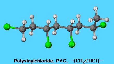
Vinyl chloride (CH2=CHCl), also known as chloroethylene, is most often obtained by reacting ethylene with oxygen and hydrogen chloride over a copper catalyst. It is a toxic and carcinogenic gas that is handled under special protective procedures. PVC is made by subjecting vinyl chloride to highly reactive compounds known as free-radical initiators. Under the action of the initiators, the double bond in the vinyl chloride monomers (single-unit molecules) is opened, and one of the resultant single bonds is used to link together thousands of vinyl chloride monomers to form the repeating units of polymers (large, multiple-unit molecules).
Pure PVC finds application in the construction trades, where its rigidity, strength, and flame resistance are useful in pipes, conduits, siding, window frames, and door frames. It is also blow-molded into clear, transparent bottles. Because of its rigidity, it must be extruded or molded below 100oC, a temperature high enough to initiate chemical decomposition, in particular, the emission of hydrogen chloride (HCl). Decomposition can be reduced by the addition of stabilizers, which are mainly compounds of metals such as cadmium, zinc, tin, or lead.
In order to arrive at a product that remains flexible, especially at low temperatures, most PVC is heated and mixed with plasticizers, which are sometimes added in concentrations as high as 50 percent. The most commonly used plasticizer is the compound di-2-ethylhexyl phthalate (DEHP), also known as dioctyl phthalate (DOP). Plasticized PVC is familiar to consumers as pipes, floor tile, garden hose, imitation leather upholstery, and shower curtains.
Very fine particles of PVC can be dispersed in plasticizer in excess of the amount used to make plasticized PVC (e.g., 50 percent or more), and this suspension can be heated until the polymer particles dissolve. The resultant fluid, called a plastisol, will remain liquid even after cooling but will solidify into a gel upon reheating. Plastisols can be made into products by being spread on fabric or cast into molds. Flexible gloves can be made by dipping a hand-shaped form into plastisol, and hollow objects such as overshoes can be made by casting plastisol into a mold, pouring off the excess, and solidifying the material remaining on the walls of the mold.
PVC has been an occasional object of controversy since a link between vinyl chloride monomer and cancer was established in 1973. Environmentalists and health advocates raised concerns over the possible ill effects of exposure to substances such as residual vinyl chloride monomer, hydrogen chloride, organometallic stabilizers, and phthalate plasticizers. Industry officials maintain that these substances are scrupulously controlled and are released from PVC in trace amounts that have not been proved harmful.
Rigid Polyvinyl Chloride (PVC) is a major plastic material which finds widespread use in building, transport, packaging, electrical/electronic and healthcare applications. PVC is a very durable and long lasting construction material which can be used in a variety of applications, either rigid or flexible, white or black and in wide range of colours. Due to its very nature, PVC is used widely in many industries and provides very many popular and necessary products. Unlike other thermoplastics which are entirely derived from oil, PVC is manufactured from two starting materials: 57% of the molecular weight derived from common salt. 43% derived from hydrocarbon feedstocks (increasingly ethylene from sugar crops is also being used for PVC production as an alternative to ethylene from oil or natural gas)
LDPE (Low Density Poly Ethylene) and LLDPE (Linear Low Density Poly Ethylene): The first of the polyolefins, Low Density Polyethylene (LDPE) was originally prepared some fifty years ago by the high pressure polymerization of ethylene. Its comparatively low density arises from the presence of a small amount of branching in the chain (on about 2% of the carbon atoms). This gives a more open structure. Low Density Polyethylene (LDPE) is a most useful and widely used plastic especially in dispensing bottles or wash bottles.
It is translucent to opaque, robust enough to be virtually unbreakable and at the same time quite flexible. Chemically LDPE is unreactive at room temperature although it is slowly attacked by strong oxidizing agents and some solvents will cause softening or swelling. It may be used at temperatures up to 95o Celsius for short periods and at 80o Celsius continuously. LDPE is ideally suited for a wide range of molded laboratory apparatus including wash bottles, pipette washing equipment, general purpose tubing, bags and small tanks.
PROPERTIES: Semi-rigid, translucent, very tough, weatherproof, good chemical resistance, low water absorption, easily processed by most methods, low cost.
HDPE (High Density Poly Ethylene): PROPERTIES: Flexible, translucent / waxy, weatherproof, good low temperature toughness (to -60oC), easy to process by most methods, low cost, good chemical resistance.
A linear polymer, High Density Polyethylene (HDPE) is prepared from ethylene by a catalytic process. The absence of branching results in a more closely packed structure with a higher density and somewhat higher chemical resistance than LDPE. HDPE is also somewhat harder and more opaque and it can withstand rather higher temperatures (120o Celsius for short periods, 110o Celsius continuously). It lends itself particularly well to blow molding, e.g. for bottles, cutting boards, dipping baskets, dippers, trays and containers.
Polypropylene is a plastic polymer with the chemical formula (C3H6)n. It is used in many different settings, both in industry and in consumer goods, and it can be used both as a structural plastic and as a fiber. This plastic is often used for food containers, particularly those that need to be dishwasher safe.
The melting point of polypropylene is very high compared to many other plastics, at 160oC), which means that the hot water used when washing dishes will not cause dishware made from this plastic to warp. This contrasts with polyethylene, another popular plastic for containers, which has a much lower melting point. Polypropylene is also very easy to add dyes to, and it is often used as a fiber in carpeting that needs to be rugged and durable, such as that for use around swimming pools or on miniature golf courses. Unlike nylon, which is also often used as a fiber for rugged carpeting, it doesn't soak up water, making it ideal for uses where it will be constantly subject to moisture.
Research is ongoing with polypropylene, as makers experiment with different methods for synthesizing it. Some of these experiments yield the promise of exciting new types of plastic, with new consistencies and a different feel from the fairly rigid version that most people are used to. These new elastic versions are very rubbery, making them even more resistant to shattering and opening up many different uses for an already pervasive plastic.
Polypropylene is not as sturdy as polyethylene, but it has benefits that make it the better choice in some situations. One of these situations is creating hinges from a plastic, such as a plastic lid on a travel mug. Over time, plastics wear out from the repetitive stress of being opened and shut, and eventually will break. Polypropylene is very resistant to this sort of stress, and it is the plastic most often used for lids and caps that require a hinging mechanism.
Like many plastics, polypropylene has virtually endless uses, and its development has not slowed since its discovery. Whether used for industrial molds, rugged currency, car parts, or storage containers, it is one of a handful of materials the world is literally built around. The properties of Polypropylene include
Semi-rigid
Translucent
Good chemical resistance
Tough
Good fatigue resistance
Integral hinge property
Good heat resistance
PP does not present stress-cracking problems and offers excellent electrical and chemical resistance at higher temperatures. While the properties of PP are similar to those of Polyethylene, there are specific differences. These include a lower density, higher softening point (PP doesn't melt below 160oC, Polyethylene, a more common plastic, will anneal at around 100oC) and higher rigidity and hardness. Additives are applied to all commercially produced polypropylene resins to protect the polymer during processing and to enhance end-use performance.
ABS (Acrylonitrile Butadiene Styrene): ABS is used for the conveyance of potable water, slurries and chemicals. Most commonly used for DWV (drain-waste-vent) applications. ABS is an ideal material wherever superlative surface quality, color fastness and luster are required. ABS is a two phase polymer blend. A continuous phase of styrene-acrylonitrile copolymer (SAN) gives the materials rigidity, hardness and heat resistance. The toughness of ABS is the result of submicroscopically fine polybutadiene rubber particles uniformly distributed in the SAN matrix.
PROPERTIES: ABS standard grades have been developed specifically to meet the requirements of major customers. ABS is readily modified both by the addition of additives and by variation of the ratio of the three monomers Acrylonitrile, Butadiene and Styrene: hence grades available include high and medium impact, high heat resistance, and electroplatable. Fiber reinforcement can be incorporated to increase stiffness and dimensional stability. ABS is readily blended or alloyed with other polymers further increasing the range of properties available. Fire retardancy may be obtained either by the inclusion of fire retardant additives or by blending with PVC. The natural material is an opaque ivory color and is readily colored with pigments or dyes. Transparent grades are also available. A variety of grades are available for different applications, the material is typically injection molded or extruded.
UPVC (unplasticized polyvinyl chloride) and CPVC (post chlorinated polyvinyl chloride): UPVC has excellent chemical resistance across its operating temperature range, with a broad band of operating pressures. It has lower amount of plasticizers. Due to its long-term strength characteristics, high stiffness and cost effectiveness, UPVC systems account for a large proportion of plastic piping installations. CPVC is resistant to many acids, bases, salts, paraffinic hydrocarbons, halogens and alcohols. It is not resistant to solvents, aromatics and some chlorinated hydrocarbons.
PVDF (polyvinylidene fluoride): PVDF has excellent chemical resistance which means that it is widely used in the chemical industry as a piping system for aggressive liquids. It is a synthetic resin produced by the polymerization of vinylidene fluoride (CH2=CF2). A tough plastic that is resistant to flame, electricity, and attack by most chemicals, PVDF is injection-molded into bottles for the chemical industry and extruded as a film for electrical insulation. Its flame resistance makes it especially desirable for insulating wire in buildings and aircraft. PVDF is also piezoelectric, changing its electrical charge in response to pressure and, conversely, exerting pressure in response to an applied electric field. This unique property makes it a good material for transducers in devices such as headphones, microphones, and sonic detectors.
The applications for PE piping products continue to expand at an accelerating rate. Gas distribution lines, potable water systems, submerged marine installations, gravity and force main sewer systems, and various types of above-ground exposed piping systems are but a few of the installations for which PE pipe and fittings have been utilized.
As piping products applications expand, so does the use of new and existing joining methods expand. A key element to this continued success is the diversity of methods available to join PE pipe and fittings. The integrity of the butt and socket fusion joining technique has been proven by the test of time in a variety of applications. The manufacturers of PE pipe and fittings have made every effort to make the systems as comprehensive as possible by producing a variety of fittings and components to insure compatibility with alternate piping materials and system appurtenances.
The purpose of this chapter has been to provide the reader with an overview of the various methods by which PE piping materials may be joined. As a result the reader has developed a further appreciation for the flexibility, integrity, and overall utility afforded in the design, installation, and performance of PE piping systems and components.
It should be noted that this chapter does not purport to address the safety considerations associated with the use of these procedures. Information on safe operating procedures can be obtained from the manufacturers of the various types of joining equipment or PE products.
Joining Method of Plastic Pipes
General Provisions: Plastic pipes or fittings are joined to each other by heat fusion or with mechanical fittings. Plastic pipe may be joined to other pipe materials by means of compression fittings, flanges, or other qualified types of manufactured transition fittings. There are many types and styles of fittings available from which the user may choose. Each offers its particular advantages and limitations for each joining situation the user may encounter. Contact with the various manufacturers is advisable for guidance in proper applications and styles available for joining as described in this document. The joining methods cover both large and small diameter pipe. Large diameter PE pipe is considered to be sizes 3” NB and larger. All individuals involved in the joining PE pipe systems, whether it be using the typical heat fusion methods or employing mechanical connections, should be fully trained and qualified in accordance with applicable codes and standards and / or as recommended by the pipe or fitting manufacturer. The equipment used in the process of making heat fused joints must be designed to operate for the selected pipe and fusion procedures. Additionally, the equipment should be well maintained and capable of operating to specification.
Thermal Heat Fusion Methods: There are three types of conventional heat fusion joints currently used in the industry; Butt, Saddle, and Socket Fusion. Additionally, electrofusion (EF) joining is available with special EF couplings and saddle fittings. The principle of heat fusion is to heat two surfaces to a designated temperature, then fuse them together by application of a sufficient force. This force causes the melted materials to flow and mix, thereby resulting in fusion. When fused according to the pipe and/or fitting manufacturers’ procedures, the joint area becomes as strong as, or stronger than, the pipe itself in both tensile and pressure properties and properly fused joints are absolutely leak proof. As soon as the joint cools to near ambient temperature, it is ready for handling.
The butt fusion machine should be capable of:
• Aligning the pipe ends
• Clamping the pipes
• Facing the pipe ends parallel and square to the centerline
• Heating the pipe ends
• Applying the proper fusion force
The six steps involved in making a butt fused joint are:
1. Clean, clamp and align the pipe ends to be joined
2. Face the pipe ends to establish clean, parallel surfaces, perpendicular to the center line
3. Align the pipe ends
4. Melt the pipe interfaces
5. Join the two pipe ends together by applying the proper fusion force
6. Hold under pressure until the joint is cool
1. Clean the pipe surface area where the saddle fitting is to be located
2. Install the appropriate size heater saddle adapters
3. Install the saddle fusion machine on the pipe
4. Prepare the surfaces of the pipe and fitting in accordance with the recommended procedures
5. Align the parts
6. Heat both the pipe and the saddle fitting
7. Press and hold the parts together
8. Cool the joint and remove the fusion machine
Follow these general steps when performing socket fusion:
1. Thoroughly clean the end of the pipe and the matching inside surface of the fitting
2. Square and prepare the pipe end
3. Heat the parts
4. Join the parts
5. Allow to cool
Equipment Selection: Select the proper size tool faces and heat the tools to the fusion temperature recommended for the material to be joined. For many years, socket fusion tools were manufactured without benefit of any industry standardization. As a result, variances of heater and socket depths and diameters, as well as depth gauges, do exist. More recently, ASTM F1056(7) was written, establishing standard dimensions for these tools. Therefore, mixing various manufacturers’ heating tools or depth gauges is not recommended unless the tools are marked “F1056,” indicating compliance with the ASTM specification and, thereby, consistency of tooling sizes.
Square and Prepare Pipe: Cut the end of the pipe square. Chamfer the pipe end for sizes 40 mm NB and larger. (Chamfering of smaller pipe sizes is acceptable and sometimes specified in the instructions.) Remove scraps, burrs, shavings, oil, or dirt from the surfaces to be joined. Clamp the cold ring on the pipe at the proper position, using the integral depth gauge pins or a separate (thimble type) depth gauge. The cold ring will assist in re- rounding the pipe and provide a stopping point for proper insertion of the pipe into the heating tool and coupling during the fusion process.
Heating: Check the heater temperature. Periodically verify the proper surface temperature using a pyrometer or other surface temperature measuring device. If temperature indicating markers are used, do not use them on a surface that will come in contact with the pipe or fitting. Bring the hot clean tool faces into contact with the outside surface of the end of the pipe and with the inside surface of the socket fitting, in accordance with pipe and fitting manufacturers’ instructions.
Joining: Simultaneously remove the pipe and fitting from the tool using a quick “snap” action. Inspect the melt pattern for uniformity and immediately insert the pipe squarely and fully into the socket of the fitting until the fitting contacts the cold ring. Do not twist the pipe or fitting during or after the insertion, as is the practice with some joining methods for other pipe materials.
Cooling: Hold or block the pipe in place so that the pipe cannot come out of the joint while the mating surfaces are cooling. These cooling times are listed in the pipe or fitting manufacturer’s instructions.
General steps to be followed when performing electro fusion joining are:
1. Prepare the pipe (scrape, clean)
2. Mark the pipe
3. Align and restrain pipe and fitting per manufacturer’s recommendations
4. Apply the electric current
5. Cool and remove the clamps
6. Document the fusion process
Prepare the Pipe (Clean and Scrape): Assure the pipe ends are cut square when joining using electro fusion couplings. The fusion area must be clean from dirt or contaminants. This may require the use of water or 90% isopropyl alcohol (NO ADDITIVES OR NOT DENATURED). Next, the pipe surface in the fusion must be scraped, that is material must be removed to expose clean virgin material. This may be achieved by various special purpose tools available from the fitting manufacturer.
Mark the Pipe: Mark the pipe for stab depth of couplings or the proper fusion location of saddles. (Caution should be taken to assure that a non-petroleum marker is used.) Align and Restrain Pipe or Fitting Per the Manufacturer’s Recommendations. Align and restrain fitting to pipe per manufacturer’s recommendations. Place the pipe(s) and fitting in the clamping fixture to prevent movement of the pipe(s) or fitting. Give special attention to proper positioning of the fitting on the prepared pipe surfaces. Large pipe diameters may need re-rounding prior to the electro fusion process.
Documenting fusion: The Electro fusion control box that applies current to the fitting also controls and monitors the critical parameters of fusion, (time, temperature, & pressure). The control box is a micro- processor capable of storing the specific fusion data for each joint. This information can be downloaded to a computer for documentation and inspection of the days work.
Heat Fusion Joining of Unlike PE Pipe and Fittings: Research has indicated that PE pipe and fittings made from unlike resins can be heat fused together to make satisfactory joints. Some gas companies have been heat-fusion joining unlike PEs for many years with success. Fusion joints, whether they involve the conventional butt, socket or saddle heat fusion assembly procedures or the electro fusion procedure, should only be made by personnel fully trained and qualified in those procedures. The equipment used shall be designed to operate for the selected pipe and fusion procedures. The equipment should be well maintained and capable of operating to specification. In addition, it is important that only the specified or recommended joining procedures be followed at all times during assembly operations.
Mechanical Connections: As in the heat fusion methods, many types of mechanical connection styles and methods are available. This section is a general description of these types of fittings. The Plastics Pipe Institute recommends that the user be well informed about the performance attributes of the particular mechanical connector being utilized. Fitting selection is important to the performance of a piping system. Product performance and application information should be available from the fitting manufacturer to assist in the selection process as well as instructions for use and performance limits, if any. Additional information for these types of products is also contained in a variety of specifications such as ASTM F1924, F1973, and AWWA C219.
The general procedures for joining would be:
1. Slip the metal ring onto the PE pipe section, far enough away from the end to avoid interference with operation of the butt fusion equipment.
2. If a stub end is used, first butt-fuse a short length of PE pipe to the pipe end of the stub end. If a “flange adapter” is used, the PE pipe-sized end is usually long enough that this step is unnecessary.
3. Butt fuse the flange adapter to the PE pipe segment.
4. The fusion bead may need to be removed to clear the back-up ring as it is moved against the flange.
5. Position the flanged face of the adapter at the position required so that the backup ring previously placed on the PE pipe segment can be attached to the metal flange.
6. Install and tighten the flange bolts in a cris-cross pattern sequence, normally used with flange type connections, drawing the metal and PE flange faces evenly and flat. Do not use the process of tightening the flanges to draw the two sections of pipe together.
Flange Gasket: A flange gasket may not be required between PE flanges. At lower pressures (typically 80 psi or less) the serrated flange sealing surface may be adequate. Gaskets may be needed for higher pressures and for connections between PE and non-PE flanges. If used, gasket materials should be chemically and thermally compatible with the internal fluid and the external environment, and should be of appropriate hardness, thickness and style. Elevated temperature applications may require higher temperature capability. Gasket thickness should be about 3-5 mm and about 60-75 Shore A hardness. Too soft or too thick gaskets may blow out under pressure. Overly hard gaskets may not seal. Common gasket styles are full-face or drop-in. Full-face style gaskets are usually applied to larger sizes, because flange bolts hold a flexible gasket in place while fitting the components together. Drop-in style gaskets are usually applied to smaller pipe sizes.
Flange Bolting: Mating flanges are usually joined together with hex bolts and hex nuts, or threaded studs and hex nuts. Bolting materials should have tensile strength equivalent to at least SAE Grade 3 for pressure pipe service, and to at least SAE Grade 2 for non-pressure service. Corrosion resistant materials should be considered for underground, underwater, or other corrosive environments. Flange bolts are sized 1/8” smaller than the blot hole diameter. Flat washers should be used between the nut and the back-up ring. Flange bolts must span the entire width of the flange joint, and provide sufficient thread length to fully engage the nut.
Flange Assembly: Mating flanges must be aligned together before tightening. Tightening misaligned flanges can cause flange assembly failure. Surface or above grade flanges must be properly supported to avoid bending stresses. Below grade flange connections to heavy appurtenances such as valves or hydrants, or to metal pipes, require a support foundation of compacted, stable granular soil (crushed stone), or compacted cement stabilized granular backfill, or reinforced concrete. Flange connections adjacent to pipes passing through structural walls must be structurally supported to avoid shear loads. Prior to fit-up, lubricate flange bolt threads, washers, and nuts with a on-fluid lubricant. Gasket and flange sealing surfaces must be clean and free of significant cuts or gouges. Fit the flange components together loosely. Hand-tighten bolts and re-check alignment. Adjust alignment if necessary. Flange bolts should be tightened to the same torque value by turning the nut. Tighten each bolt according to the patterns and torques recommended by the flange manufacturer. PE and the gasket (if used) will undergo some compression set. Therefore, retightening is recommended about an hour or so after torquing to the final torque value the first time. In crisscross pattern sequence, retighten each bolt to the final torque value. For high pressure or environmentally sensitive or critical pipelines, a third tightening, about 4 hours after the second, is recommended.
Special Cases: When flanging to brittle materials such as cast iron, accurate alignment, and careful tightening are necessary. Tightening torque increments should not exceed 10 ft.-lbs. PE flange adapters and stub ends are not full-face, so tightening places a bending stress across the flange face. Over-tightening, misalignment, or uneven tightening can break brittle material flanges. When joining a PE flange adapter or stub end to a flanged butterfly valve, the inside diameter of the pipe flange should be checked for valve disk rotation clearance. The open valve disk may extend into the body of the flange adapter/stub end. Valve operation may be restricted if the pipe flange interferes with the disk. If disk rotation clearance is a problem, a tubular spacer may be installed between the mating flanges, or the pipe flange bore may be chamfered slightly. At the sealing surface, chamfering must not increase the flange inside diameter by more than 10%, and not extend into the flange more than 20% of the flange thickness. If spacer plates are used, the flange bolt length must be increased by the length of the spacer.
Restraint Methods: A pipe section with fully restrained joints such as a long string of butt fused PE pipe will transmit Poisson effect pipe shortening from length to length through the restrained joints along the pipe string. Restrained joints include butt fusions, electro-fusions, socket fusions, bolted flange connections, MJ Adapter connections or other restrained mechanical connections. If an unrestrained bell and spigot or mechanical sleeve joint is in-line with the restrained section, the cumulative Poisson effect shortening and possible thermal expansion / contraction effect may cause in-line unrestrained joints or connections to be pulled apart. Therefore, unrestrained joints or mechanical connections that are in-line with fully restrained PE pipe must be either restrained or otherwise protected against pullout disjoining.
Pipe: The range of pipe diameters for each pipe system does vary. However, the size ranges from 12 to 400 mm. Pipes are extruded and are generally available in: 3 m, 4 m, 5 m, and 6 m straight lengths and 25 m, 50 m, 100 m, and 200 m coils for LDPE and MDPE.
Plastic piping is used in various sectors including mining, building and industrial. Applications include: water and sewerage reticulation, drainage and discharge systems, construction, irrigation, mining, water, slurry, acid.
HDPE and PP range includes Compression Fittings and Saddles, Thermoplastic Valves and Fittings, Bends, T-pieces, Laterals, Spool Pieces, Manufactured Steel Saddles, Piping And Coils, Jointing Systems.
Polyethylene pipes have yielded excellent results when used in different mining applications. Owing to their high abrasion and corrosion resistance, ease of handling of installation and their high mechanical strength, they are ideal for:
Irrigating leaching piles Conveying acid and alkaline solutions, Concentrate pipelines (Reduction works and Drainage), Fire fighting installations, Drinking water lines, Chilled water lines, Compressed air lines, Ventilation ducting, Vacuum lines.
Fittings are molded and come in many sizes: tee 90° equal (straight and reducing), tee 45°, cross equal, elbow 90° (straight and reducing), elbow 45°, short radius bend 90° socket/coupler (straight and reducing), union, end caps, reducing bush, and stub, full face, and blanking flanges.
Valves are moulded and also come in many types: ball valve (also multi port), butterfly valve, spring-, ball-, and swing-check non-return valves, diaphragm valve, knife gate valve, globe valve and pressure relief/reduction valves.
Vinyl chloride (CH2=CHCl), also known as chloroethylene, is most often obtained by reacting ethylene with oxygen and hydrogen chloride over a copper catalyst. It is a toxic and carcinogenic gas that is handled under special protective procedures. PVC is made by subjecting vinyl chloride to highly reactive compounds known as free-radical initiators. Under the action of the initiators, the double bond in the vinyl chloride monomers (single-unit molecules) is opened, and one of the resultant single bonds is used to link together thousands of vinyl chloride monomers to form the repeating units of polymers (large, multiple-unit molecules).
Pure PVC finds application in the construction trades, where its rigidity, strength, and flame resistance are useful in pipes, conduits, siding, window frames, and door frames. It is also blow-molded into clear, transparent bottles. Because of its rigidity, it must be extruded or molded below 100oC, a temperature high enough to initiate chemical decomposition, in particular, the emission of hydrogen chloride (HCl). Decomposition can be reduced by the addition of stabilizers, which are mainly compounds of metals such as cadmium, zinc, tin, or lead.
In order to arrive at a product that remains flexible, especially at low temperatures, most PVC is heated and mixed with plasticizers, which are sometimes added in concentrations as high as 50 percent. The most commonly used plasticizer is the compound di-2-ethylhexyl phthalate (DEHP), also known as dioctyl phthalate (DOP). Plasticized PVC is familiar to consumers as pipes, floor tile, garden hose, imitation leather upholstery, and shower curtains.
Very fine particles of PVC can be dispersed in plasticizer in excess of the amount used to make plasticized PVC (e.g., 50 percent or more), and this suspension can be heated until the polymer particles dissolve. The resultant fluid, called a plastisol, will remain liquid even after cooling but will solidify into a gel upon reheating. Plastisols can be made into products by being spread on fabric or cast into molds. Flexible gloves can be made by dipping a hand-shaped form into plastisol, and hollow objects such as overshoes can be made by casting plastisol into a mold, pouring off the excess, and solidifying the material remaining on the walls of the mold.
PVC has been an occasional object of controversy since a link between vinyl chloride monomer and cancer was established in 1973. Environmentalists and health advocates raised concerns over the possible ill effects of exposure to substances such as residual vinyl chloride monomer, hydrogen chloride, organometallic stabilizers, and phthalate plasticizers. Industry officials maintain that these substances are scrupulously controlled and are released from PVC in trace amounts that have not been proved harmful.
Rigid Polyvinyl Chloride (PVC) is a major plastic material which finds widespread use in building, transport, packaging, electrical/electronic and healthcare applications. PVC is a very durable and long lasting construction material which can be used in a variety of applications, either rigid or flexible, white or black and in wide range of colours. Due to its very nature, PVC is used widely in many industries and provides very many popular and necessary products. Unlike other thermoplastics which are entirely derived from oil, PVC is manufactured from two starting materials: 57% of the molecular weight derived from common salt. 43% derived from hydrocarbon feedstocks (increasingly ethylene from sugar crops is also being used for PVC production as an alternative to ethylene from oil or natural gas)
|
PHYSICAL PROPERTIES Tensile Strength 2.60 N/mm2 Notched Impact Strength 2.0 - 45 Kj/m2 Thermal Coefficient of expansion 80 x 10-6 Max Cont Use Temp 60oC Density 1.38 g/cm3 |
RESISTANCE TO CHEMICALS Dilute Acid : very good Dilute Alkalis : very good Oils and Greases : good variable Aliphatic Hydrocarbons : very good Aromatic Hydrocarbons : poor Halogenated Hydrocarbons : moderate variable Alcohols : good variable |
LDPE (Low Density Poly Ethylene) and LLDPE (Linear Low Density Poly Ethylene): The first of the polyolefins, Low Density Polyethylene (LDPE) was originally prepared some fifty years ago by the high pressure polymerization of ethylene. Its comparatively low density arises from the presence of a small amount of branching in the chain (on about 2% of the carbon atoms). This gives a more open structure. Low Density Polyethylene (LDPE) is a most useful and widely used plastic especially in dispensing bottles or wash bottles.
It is translucent to opaque, robust enough to be virtually unbreakable and at the same time quite flexible. Chemically LDPE is unreactive at room temperature although it is slowly attacked by strong oxidizing agents and some solvents will cause softening or swelling. It may be used at temperatures up to 95o Celsius for short periods and at 80o Celsius continuously. LDPE is ideally suited for a wide range of molded laboratory apparatus including wash bottles, pipette washing equipment, general purpose tubing, bags and small tanks.
PROPERTIES: Semi-rigid, translucent, very tough, weatherproof, good chemical resistance, low water absorption, easily processed by most methods, low cost.
|
PHYSICAL PROPERTIES Tensile Strength 0.20 - 0.40 N/mm2 Notched Impact Strength no break Kj/m2 Thermal Coefficient of expansion 100 - 220 x 10-6 Max Cont Use Temp 65oC Density 0.917 - 0.930 g/cm3 |
RESISTANCE TO CHEMICALS Dilute Acid : very good Dilute Alkalis : very good Oils and Greases : moderate variable Aliphatic Hydrocarbons : poor Aromatic Hydrocarbons : poor Halogenated Hydrocarbons : poor Alcohols : very good |
HDPE (High Density Poly Ethylene): PROPERTIES: Flexible, translucent / waxy, weatherproof, good low temperature toughness (to -60oC), easy to process by most methods, low cost, good chemical resistance.
A linear polymer, High Density Polyethylene (HDPE) is prepared from ethylene by a catalytic process. The absence of branching results in a more closely packed structure with a higher density and somewhat higher chemical resistance than LDPE. HDPE is also somewhat harder and more opaque and it can withstand rather higher temperatures (120o Celsius for short periods, 110o Celsius continuously). It lends itself particularly well to blow molding, e.g. for bottles, cutting boards, dipping baskets, dippers, trays and containers.
|
PHYSICAL PROPERTIES Tensile Strength 0.20 - 0.40 N/mm2 Notched Impact Strength no break Kj/m2 Thermal Coefficient of expansion 100 - 220 x 10-6 Max Cont Use Temp 65oC Density 0.944 - 0.965 g/cm3 |
RESISTANCE TO CHEMICALS Dilute Acid : very good Dilute Alkalis : very good Oils and Greases : moderate variable Aliphatic Hydrocarbons : poor Aromatic Hydrocarbons : poor Halogenated Hydrocarbons : poor Alcohols : very good |
Polypropylene is a plastic polymer with the chemical formula (C3H6)n. It is used in many different settings, both in industry and in consumer goods, and it can be used both as a structural plastic and as a fiber. This plastic is often used for food containers, particularly those that need to be dishwasher safe.
The melting point of polypropylene is very high compared to many other plastics, at 160oC), which means that the hot water used when washing dishes will not cause dishware made from this plastic to warp. This contrasts with polyethylene, another popular plastic for containers, which has a much lower melting point. Polypropylene is also very easy to add dyes to, and it is often used as a fiber in carpeting that needs to be rugged and durable, such as that for use around swimming pools or on miniature golf courses. Unlike nylon, which is also often used as a fiber for rugged carpeting, it doesn't soak up water, making it ideal for uses where it will be constantly subject to moisture.
Research is ongoing with polypropylene, as makers experiment with different methods for synthesizing it. Some of these experiments yield the promise of exciting new types of plastic, with new consistencies and a different feel from the fairly rigid version that most people are used to. These new elastic versions are very rubbery, making them even more resistant to shattering and opening up many different uses for an already pervasive plastic.
Polypropylene is not as sturdy as polyethylene, but it has benefits that make it the better choice in some situations. One of these situations is creating hinges from a plastic, such as a plastic lid on a travel mug. Over time, plastics wear out from the repetitive stress of being opened and shut, and eventually will break. Polypropylene is very resistant to this sort of stress, and it is the plastic most often used for lids and caps that require a hinging mechanism.
Like many plastics, polypropylene has virtually endless uses, and its development has not slowed since its discovery. Whether used for industrial molds, rugged currency, car parts, or storage containers, it is one of a handful of materials the world is literally built around. The properties of Polypropylene include
Semi-rigid
Translucent
Good chemical resistance
Tough
Good fatigue resistance
Integral hinge property
Good heat resistance
PP does not present stress-cracking problems and offers excellent electrical and chemical resistance at higher temperatures. While the properties of PP are similar to those of Polyethylene, there are specific differences. These include a lower density, higher softening point (PP doesn't melt below 160oC, Polyethylene, a more common plastic, will anneal at around 100oC) and higher rigidity and hardness. Additives are applied to all commercially produced polypropylene resins to protect the polymer during processing and to enhance end-use performance.
ABS (Acrylonitrile Butadiene Styrene): ABS is used for the conveyance of potable water, slurries and chemicals. Most commonly used for DWV (drain-waste-vent) applications. ABS is an ideal material wherever superlative surface quality, color fastness and luster are required. ABS is a two phase polymer blend. A continuous phase of styrene-acrylonitrile copolymer (SAN) gives the materials rigidity, hardness and heat resistance. The toughness of ABS is the result of submicroscopically fine polybutadiene rubber particles uniformly distributed in the SAN matrix.
PROPERTIES: ABS standard grades have been developed specifically to meet the requirements of major customers. ABS is readily modified both by the addition of additives and by variation of the ratio of the three monomers Acrylonitrile, Butadiene and Styrene: hence grades available include high and medium impact, high heat resistance, and electroplatable. Fiber reinforcement can be incorporated to increase stiffness and dimensional stability. ABS is readily blended or alloyed with other polymers further increasing the range of properties available. Fire retardancy may be obtained either by the inclusion of fire retardant additives or by blending with PVC. The natural material is an opaque ivory color and is readily colored with pigments or dyes. Transparent grades are also available. A variety of grades are available for different applications, the material is typically injection molded or extruded.
|
PHYSICAL PROPERTIES Tensile Strength: 40-50 Mpa Notched Impact Strength: 10 - 20 Kj/m2 Thermal Coefficient of expansion: 70 - 90 x 10-6 Max Cont Use Temp: 80 - 95oC Density: 1.0 - 1.05 g/cm3 |
RESISTANCE TO CHEMICALS Dilute Acid : very good Dilute Alkalis : very good Oils and Greases : very good Aliphatic Hydrocarbons : moderate Aromatic Hydrocarbons : poor Halogenated Hydrocarbons : poor Alcohols : poor (variable) |
UPVC (unplasticized polyvinyl chloride) and CPVC (post chlorinated polyvinyl chloride): UPVC has excellent chemical resistance across its operating temperature range, with a broad band of operating pressures. It has lower amount of plasticizers. Due to its long-term strength characteristics, high stiffness and cost effectiveness, UPVC systems account for a large proportion of plastic piping installations. CPVC is resistant to many acids, bases, salts, paraffinic hydrocarbons, halogens and alcohols. It is not resistant to solvents, aromatics and some chlorinated hydrocarbons.
PVDF (polyvinylidene fluoride): PVDF has excellent chemical resistance which means that it is widely used in the chemical industry as a piping system for aggressive liquids. It is a synthetic resin produced by the polymerization of vinylidene fluoride (CH2=CF2). A tough plastic that is resistant to flame, electricity, and attack by most chemicals, PVDF is injection-molded into bottles for the chemical industry and extruded as a film for electrical insulation. Its flame resistance makes it especially desirable for insulating wire in buildings and aircraft. PVDF is also piezoelectric, changing its electrical charge in response to pressure and, conversely, exerting pressure in response to an applied electric field. This unique property makes it a good material for transducers in devices such as headphones, microphones, and sonic detectors.
The applications for PE piping products continue to expand at an accelerating rate. Gas distribution lines, potable water systems, submerged marine installations, gravity and force main sewer systems, and various types of above-ground exposed piping systems are but a few of the installations for which PE pipe and fittings have been utilized.
As piping products applications expand, so does the use of new and existing joining methods expand. A key element to this continued success is the diversity of methods available to join PE pipe and fittings. The integrity of the butt and socket fusion joining technique has been proven by the test of time in a variety of applications. The manufacturers of PE pipe and fittings have made every effort to make the systems as comprehensive as possible by producing a variety of fittings and components to insure compatibility with alternate piping materials and system appurtenances.
The purpose of this chapter has been to provide the reader with an overview of the various methods by which PE piping materials may be joined. As a result the reader has developed a further appreciation for the flexibility, integrity, and overall utility afforded in the design, installation, and performance of PE piping systems and components.
It should be noted that this chapter does not purport to address the safety considerations associated with the use of these procedures. Information on safe operating procedures can be obtained from the manufacturers of the various types of joining equipment or PE products.
Thermal Heat Fusion Methods: There are three types of conventional heat fusion joints currently used in the industry; Butt, Saddle, and Socket Fusion. Additionally, electrofusion (EF) joining is available with special EF couplings and saddle fittings. The principle of heat fusion is to heat two surfaces to a designated temperature, then fuse them together by application of a sufficient force. This force causes the melted materials to flow and mix, thereby resulting in fusion. When fused according to the pipe and/or fitting manufacturers’ procedures, the joint area becomes as strong as, or stronger than, the pipe itself in both tensile and pressure properties and properly fused joints are absolutely leak proof. As soon as the joint cools to near ambient temperature, it is ready for handling.
The butt fusion machine should be capable of:
• Aligning the pipe ends
• Clamping the pipes
• Facing the pipe ends parallel and square to the centerline
• Heating the pipe ends
• Applying the proper fusion force
The six steps involved in making a butt fused joint are:
1. Clean, clamp and align the pipe ends to be joined
2. Face the pipe ends to establish clean, parallel surfaces, perpendicular to the center line
3. Align the pipe ends
4. Melt the pipe interfaces
5. Join the two pipe ends together by applying the proper fusion force
6. Hold under pressure until the joint is cool
1. Clean the pipe surface area where the saddle fitting is to be located
2. Install the appropriate size heater saddle adapters
3. Install the saddle fusion machine on the pipe
4. Prepare the surfaces of the pipe and fitting in accordance with the recommended procedures
5. Align the parts
6. Heat both the pipe and the saddle fitting
7. Press and hold the parts together
8. Cool the joint and remove the fusion machine
Follow these general steps when performing socket fusion:
1. Thoroughly clean the end of the pipe and the matching inside surface of the fitting
2. Square and prepare the pipe end
3. Heat the parts
4. Join the parts
5. Allow to cool
Equipment Selection: Select the proper size tool faces and heat the tools to the fusion temperature recommended for the material to be joined. For many years, socket fusion tools were manufactured without benefit of any industry standardization. As a result, variances of heater and socket depths and diameters, as well as depth gauges, do exist. More recently, ASTM F1056(7) was written, establishing standard dimensions for these tools. Therefore, mixing various manufacturers’ heating tools or depth gauges is not recommended unless the tools are marked “F1056,” indicating compliance with the ASTM specification and, thereby, consistency of tooling sizes.
Square and Prepare Pipe: Cut the end of the pipe square. Chamfer the pipe end for sizes 40 mm NB and larger. (Chamfering of smaller pipe sizes is acceptable and sometimes specified in the instructions.) Remove scraps, burrs, shavings, oil, or dirt from the surfaces to be joined. Clamp the cold ring on the pipe at the proper position, using the integral depth gauge pins or a separate (thimble type) depth gauge. The cold ring will assist in re- rounding the pipe and provide a stopping point for proper insertion of the pipe into the heating tool and coupling during the fusion process.
Heating: Check the heater temperature. Periodically verify the proper surface temperature using a pyrometer or other surface temperature measuring device. If temperature indicating markers are used, do not use them on a surface that will come in contact with the pipe or fitting. Bring the hot clean tool faces into contact with the outside surface of the end of the pipe and with the inside surface of the socket fitting, in accordance with pipe and fitting manufacturers’ instructions.
Joining: Simultaneously remove the pipe and fitting from the tool using a quick “snap” action. Inspect the melt pattern for uniformity and immediately insert the pipe squarely and fully into the socket of the fitting until the fitting contacts the cold ring. Do not twist the pipe or fitting during or after the insertion, as is the practice with some joining methods for other pipe materials.
Cooling: Hold or block the pipe in place so that the pipe cannot come out of the joint while the mating surfaces are cooling. These cooling times are listed in the pipe or fitting manufacturer’s instructions.
General steps to be followed when performing electro fusion joining are:
1. Prepare the pipe (scrape, clean)
2. Mark the pipe
3. Align and restrain pipe and fitting per manufacturer’s recommendations
4. Apply the electric current
5. Cool and remove the clamps
6. Document the fusion process
Prepare the Pipe (Clean and Scrape): Assure the pipe ends are cut square when joining using electro fusion couplings. The fusion area must be clean from dirt or contaminants. This may require the use of water or 90% isopropyl alcohol (NO ADDITIVES OR NOT DENATURED). Next, the pipe surface in the fusion must be scraped, that is material must be removed to expose clean virgin material. This may be achieved by various special purpose tools available from the fitting manufacturer.
Mark the Pipe: Mark the pipe for stab depth of couplings or the proper fusion location of saddles. (Caution should be taken to assure that a non-petroleum marker is used.) Align and Restrain Pipe or Fitting Per the Manufacturer’s Recommendations. Align and restrain fitting to pipe per manufacturer’s recommendations. Place the pipe(s) and fitting in the clamping fixture to prevent movement of the pipe(s) or fitting. Give special attention to proper positioning of the fitting on the prepared pipe surfaces. Large pipe diameters may need re-rounding prior to the electro fusion process.
Documenting fusion: The Electro fusion control box that applies current to the fitting also controls and monitors the critical parameters of fusion, (time, temperature, & pressure). The control box is a micro- processor capable of storing the specific fusion data for each joint. This information can be downloaded to a computer for documentation and inspection of the days work.
Heat Fusion Joining of Unlike PE Pipe and Fittings: Research has indicated that PE pipe and fittings made from unlike resins can be heat fused together to make satisfactory joints. Some gas companies have been heat-fusion joining unlike PEs for many years with success. Fusion joints, whether they involve the conventional butt, socket or saddle heat fusion assembly procedures or the electro fusion procedure, should only be made by personnel fully trained and qualified in those procedures. The equipment used shall be designed to operate for the selected pipe and fusion procedures. The equipment should be well maintained and capable of operating to specification. In addition, it is important that only the specified or recommended joining procedures be followed at all times during assembly operations.
Mechanical Connections: As in the heat fusion methods, many types of mechanical connection styles and methods are available. This section is a general description of these types of fittings. The Plastics Pipe Institute recommends that the user be well informed about the performance attributes of the particular mechanical connector being utilized. Fitting selection is important to the performance of a piping system. Product performance and application information should be available from the fitting manufacturer to assist in the selection process as well as instructions for use and performance limits, if any. Additional information for these types of products is also contained in a variety of specifications such as ASTM F1924, F1973, and AWWA C219.
The general procedures for joining would be:
1. Slip the metal ring onto the PE pipe section, far enough away from the end to avoid interference with operation of the butt fusion equipment.
2. If a stub end is used, first butt-fuse a short length of PE pipe to the pipe end of the stub end. If a “flange adapter” is used, the PE pipe-sized end is usually long enough that this step is unnecessary.
3. Butt fuse the flange adapter to the PE pipe segment.
4. The fusion bead may need to be removed to clear the back-up ring as it is moved against the flange.
5. Position the flanged face of the adapter at the position required so that the backup ring previously placed on the PE pipe segment can be attached to the metal flange.
6. Install and tighten the flange bolts in a cris-cross pattern sequence, normally used with flange type connections, drawing the metal and PE flange faces evenly and flat. Do not use the process of tightening the flanges to draw the two sections of pipe together.
Flange Gasket: A flange gasket may not be required between PE flanges. At lower pressures (typically 80 psi or less) the serrated flange sealing surface may be adequate. Gaskets may be needed for higher pressures and for connections between PE and non-PE flanges. If used, gasket materials should be chemically and thermally compatible with the internal fluid and the external environment, and should be of appropriate hardness, thickness and style. Elevated temperature applications may require higher temperature capability. Gasket thickness should be about 3-5 mm and about 60-75 Shore A hardness. Too soft or too thick gaskets may blow out under pressure. Overly hard gaskets may not seal. Common gasket styles are full-face or drop-in. Full-face style gaskets are usually applied to larger sizes, because flange bolts hold a flexible gasket in place while fitting the components together. Drop-in style gaskets are usually applied to smaller pipe sizes.
Flange Bolting: Mating flanges are usually joined together with hex bolts and hex nuts, or threaded studs and hex nuts. Bolting materials should have tensile strength equivalent to at least SAE Grade 3 for pressure pipe service, and to at least SAE Grade 2 for non-pressure service. Corrosion resistant materials should be considered for underground, underwater, or other corrosive environments. Flange bolts are sized 1/8” smaller than the blot hole diameter. Flat washers should be used between the nut and the back-up ring. Flange bolts must span the entire width of the flange joint, and provide sufficient thread length to fully engage the nut.
Flange Assembly: Mating flanges must be aligned together before tightening. Tightening misaligned flanges can cause flange assembly failure. Surface or above grade flanges must be properly supported to avoid bending stresses. Below grade flange connections to heavy appurtenances such as valves or hydrants, or to metal pipes, require a support foundation of compacted, stable granular soil (crushed stone), or compacted cement stabilized granular backfill, or reinforced concrete. Flange connections adjacent to pipes passing through structural walls must be structurally supported to avoid shear loads. Prior to fit-up, lubricate flange bolt threads, washers, and nuts with a on-fluid lubricant. Gasket and flange sealing surfaces must be clean and free of significant cuts or gouges. Fit the flange components together loosely. Hand-tighten bolts and re-check alignment. Adjust alignment if necessary. Flange bolts should be tightened to the same torque value by turning the nut. Tighten each bolt according to the patterns and torques recommended by the flange manufacturer. PE and the gasket (if used) will undergo some compression set. Therefore, retightening is recommended about an hour or so after torquing to the final torque value the first time. In crisscross pattern sequence, retighten each bolt to the final torque value. For high pressure or environmentally sensitive or critical pipelines, a third tightening, about 4 hours after the second, is recommended.
Special Cases: When flanging to brittle materials such as cast iron, accurate alignment, and careful tightening are necessary. Tightening torque increments should not exceed 10 ft.-lbs. PE flange adapters and stub ends are not full-face, so tightening places a bending stress across the flange face. Over-tightening, misalignment, or uneven tightening can break brittle material flanges. When joining a PE flange adapter or stub end to a flanged butterfly valve, the inside diameter of the pipe flange should be checked for valve disk rotation clearance. The open valve disk may extend into the body of the flange adapter/stub end. Valve operation may be restricted if the pipe flange interferes with the disk. If disk rotation clearance is a problem, a tubular spacer may be installed between the mating flanges, or the pipe flange bore may be chamfered slightly. At the sealing surface, chamfering must not increase the flange inside diameter by more than 10%, and not extend into the flange more than 20% of the flange thickness. If spacer plates are used, the flange bolt length must be increased by the length of the spacer.
Restraint Methods: A pipe section with fully restrained joints such as a long string of butt fused PE pipe will transmit Poisson effect pipe shortening from length to length through the restrained joints along the pipe string. Restrained joints include butt fusions, electro-fusions, socket fusions, bolted flange connections, MJ Adapter connections or other restrained mechanical connections. If an unrestrained bell and spigot or mechanical sleeve joint is in-line with the restrained section, the cumulative Poisson effect shortening and possible thermal expansion / contraction effect may cause in-line unrestrained joints or connections to be pulled apart. Therefore, unrestrained joints or mechanical connections that are in-line with fully restrained PE pipe must be either restrained or otherwise protected against pullout disjoining.
 to get all the information as a eBook
