 |
Satish Lele lelepiping@gmail.com |
View this page as YouTube Video Presentation
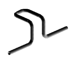
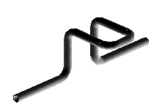
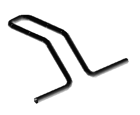
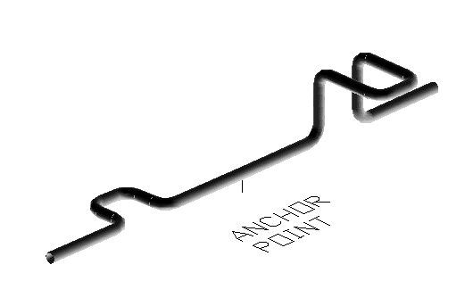
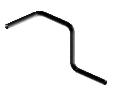
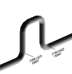
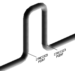
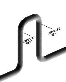
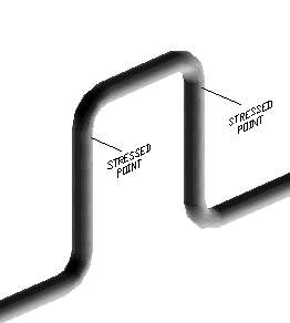
When hot fluid passes through a pipe line, the pipe line expands along its length. When the fluid stops flowing or if line is emptied, it cools and contracts to original length. If the pipe is running on grade or pipe rack, it is generally quite long and it may increase in length by 50 mm. To compensate for the change in length, expansion loops are provided. The expansion loops absorb the increase in length by deflecting. These are of different types. The loop can be in one direction. The direction is decided on the basis of availability of space.
U Bends
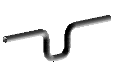
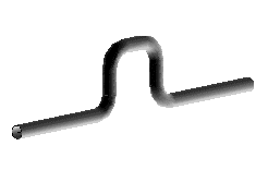
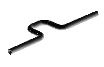
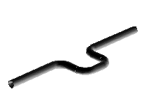
The following form loop in two directions. The top center point of loop rests on structure.
Understanding of material classification systems, material specifications, and material properties is often limited to a few grades of carbon steel or to a specific alloy system employed by the user on a regular basis. B31.3 is a safety code focusing primarily on mechanical design, mechanical properties, and resulting pressure integrity.
Material Classification Systems and Specifications: Three primary methods of identifying materials are:
a) generic designations
b) trade names or proprietary designations
c) standardized alphanumeric designations
These material designation systems are discussed in more detail in the table.

FABRICATION, ASSEMBLY, AND ERECTION


- Diameter of the pipe
- Thickness of the pipe
- Temperature of material flowing through the pipe
- Material of Construction of the pipe
- Weights of fittings like elbows, tees, valves etc.


Understanding of material classification systems, material specifications, and material properties is often limited to a few grades of carbon steel or to a specific alloy system employed by the user on a regular basis. B31.3 is a safety code focusing primarily on mechanical design, mechanical properties, and resulting pressure integrity.
Material Classification Systems and Specifications: Three primary methods of identifying materials are:
a) generic designations
b) trade names or proprietary designations
c) standardized alphanumeric designations
These material designation systems are discussed in more detail in the table.

FABRICATION, ASSEMBLY, AND ERECTION
- Fabrication is the preparation of piping for assembly, including cutting, threading, grooving, forming, bending, and joining of components into subassemblies. Fabrication may be performed in the shop or in the field.
- Assembly is the joining together of two or more piping components by bolting, welding, bonding, screwing, brazing, soldering, cementing, or use of packing devices as specified by the engineering design.
- Erection is the complete installation of a piping system in the locations and on the supports designated by the engineering design, including any field assembly, fabrication, examination, inspection, and testing of the system as required by the Code.
- forming and bending by cold and hot methods
- joining by welding, brazing, soldering, or mechanical methods including threading, flanging, specialty high pressure connections, and mechanical interference fits (MIF)
- heat treatment by local methods, or by permanent or temporary furnaces
- method of manufacture, including cold bends, hot bends, furnace bends, induction bends, arm bends, ram bends, three point bends, miter bends, segmented bends, corrugated bends, and creased bends
- location of manufacture, that is, field bends or factory bends
- shape or appearance, such as L-bends, S-bends, wrinkle bends, miter bends, segmented bends, corrugated bends, and creased bends
- function or end use, such as sag bends, over bends, side bends, and combination bends
 to get all the information as a eBook
